
Arduino LED Dimmer

The schematic design process in CadSoft Eagle involves several key steps and considerations to ensure a functional and efficient electronic circuit. The selection of components is critical, as it affects both the performance and the feasibility of the project. The use of libraries such as those provided by Adafruit and Sparkfun aids in this selection, as they contain a variety of pre-designed components that can be easily integrated into the schematic.
When creating the schematic, attention must be paid to the connections between components. Properly laying out the circuit ensures that signals flow correctly and reduces the likelihood of errors during the manufacturing process. The schematic should clearly represent the relationships between different components, including power supply connections, signal paths, and ground connections.
The inclusion of headers for ICSP (In-Circuit Serial Programming) and TTL Serial communication is particularly important for projects involving microcontrollers, as these interfaces facilitate programming and debugging. The breakout connections for analog inputs and interrupt pins provide flexibility for future expansions or modifications to the circuit, allowing for greater versatility in application.
It is also essential to verify that each component's footprint matches the physical dimensions required for PCB fabrication. Mismatched footprints can lead to assembly issues and may necessitate additional design iterations. By referencing existing schematics, such as the Adafruit Boarduino and Standalone Arduino, the designer can gain insights into effective layouts and component arrangements.
Once the schematic is complete, it can be used to generate a PCB layout, where the physical placement of components and routing of traces will occur. This transition from schematic to layout is a crucial step in the design process, as it directly impacts the manufacturability and reliability of the final product. Proper design practices, such as maintaining adequate spacing between traces and ensuring proper grounding, will contribute to the overall success of the project.First thing`s first, what software to use I went with CadSoft Eagle primarily because there are lots of tutorials out there covering it, and that seemed like a good place to start. Once I understand the process I can worry about what software I use, but for now, there`s a free-to-use version of Eagle, it`ll do.
On my Kubuntu box, installing Eagle was just a case of installing the eagle package. For the Mac I had to download the installer from CadSoft`s website. I also downloaded and installedthe Sparkfun Eagle Library and the Adafruit Eagle Library. They really helped to simplify things, though I did find that I had to modify one or two of the packages, mainly just prettifying the silkscreen. I just couldn`t help myself! I`m going to skip theintricaciesof using Eagle, these posts are really just a log of what I`ve been up to and my own commentary on the process.
There are plenty of tutorials out there on how to use Eagle. A good place to start would be the Sparkfun Beginning Embedded Electronics Tutorials. Eagle`s UI is unlike any I`ve come across. I`m still not quite sure if it`s genius or justreallyold. I suspect it`s the latter and that the paradigm used to interact with a computer has somewhat shifted since it`s day. However, if it ain`t broke, don`t fix it, and if you`re clever enough to be designing electronics, then you`re clever enough to work it!
All I will say is that there are times when it seems staggeringlycounter-intuitive, particularlythe library editor. Also, I found the naming conventions used in some of the component libraries to be perverse. Yeah-yeah, I know, don`t blame the libraries, blame the person who doesn`t know what he`s looking at!
All I`m saying is, the component descriptions could be a little more descriptive! Once Eagle was installed and I`d gone though a couple of tutorials, it was time to draw out the schematic. That, I found to be fairly straightforward, more time consuming however was finding the right parts from the vast libraries and making sure the part had the right footprint.
I mostly referenced the Adafruit Boarduino schematic and the Standalone Arduino. I did look at the official Arduino Duemilanove schematic, since that`s the board I have. But on taking one look at the board layout, I quickly realised there`s a little more going on with them than I needed on my boards! So rather than hack down a large schematic at the risk of breaking it, I figured I`d just find asimplerone to begin with!
Most of the components I wanted, I found in the Adafruit or Sparkfun libraries, including some handy variations on standard parts, such as the ICSP and TTL Serial headers with the pinslabelled. Resistors and capacitors are in the rcl library and the 7805 regulator was in the linear library.
Rcl and Linear are standard libraries that come with Eagle, for navigating those, I stumbled across a list of common components and where to find them. I quickly bookmarked that before I lost it! Here you can see the ATMega chip (left), the TLC5940 (right) and the various other bits of supportingcircuitryaround them.
I broke out the ICSP and TTL Serial headers, as well breaking out the analogue inputs and an interruptpin. Since I have no specific use in mind for these dimmers but rather a multitude of rough ideas, I`m keeping my options open.
TTL serial, I2C, and six GPIO pins complete with ADCs, I think that should just about cover it! 🔗 External reference
Related Circuits
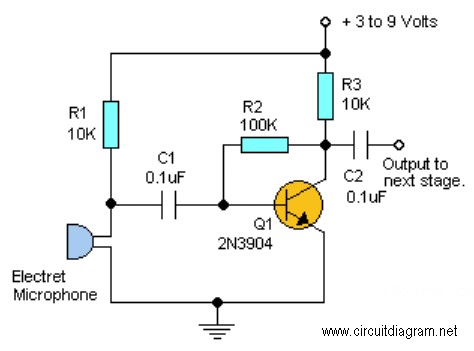
Read the generic sound level from an electret microphone. Several schematics utilize NPN transistors that yield an inverted output (~5V when quiet, ~0V when loud, with linear operation in between). However, a non-inverted output is desired, where a super...
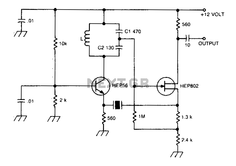
A typical Butler oscillator operating within the frequency range of 20 to 100 MHz incorporates a Field Effect Transistor (FET) in the second stage of its configuration. The circuit exhibits reliability issues when utilizing two bipolar transistors. In some...
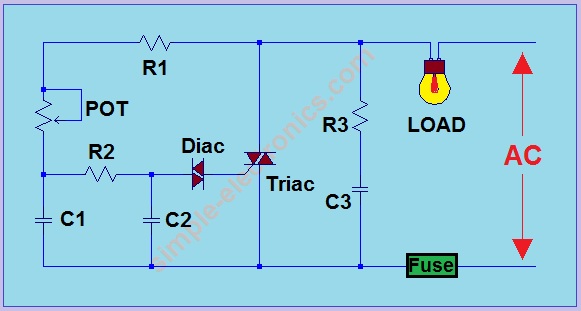
Note: Do not build or use this if you do not have any knowledge in electrical or electronics. This project is not safe for beginners, and the voltage involved is dangerous and can cause electrocution. Do not exceed the...
A boost converter, such as the TPS61160/1, can be utilized with a 40V rated integrated switch FET to drive multiple LEDs in series. This configuration can help reduce output ripple. The TPS61160/1 is a highly efficient boost converter designed for...
This project requires expensive hardware, including a microphone and amplifier, along with sophisticated audio analysis on the microcontroller. Even a complete microphone with an amplifier circuit does not yield the desired results, as noted in the product comments. The...
This is a 0 - 6 MHz DDS VFO controlled by a PIC16F84 (or C84). The VFO is separated into two modules, the DDS module and the controller module. The PCB layout (double sided) for the DDS module is...