
Modified 220V Dimmer Circuit
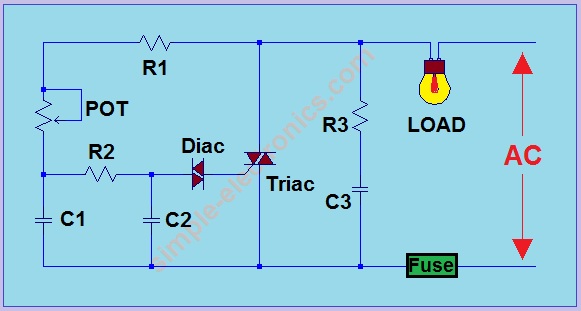
This project involves the design and implementation of a high-power electrical circuit, which operates at 220VAC and is capable of handling loads up to 600W. Due to the high voltage levels and potential hazards associated with electrical projects, it is imperative that only individuals with a solid understanding of electrical engineering principles undertake this project.
The circuit should incorporate appropriate safety mechanisms, such as fuses or circuit breakers, to prevent overload conditions that could lead to equipment damage or personal injury. Isolation transformers may also be utilized to enhance safety by providing galvanic isolation between the mains supply and the load.
It is essential to ensure that all components used in the circuit are rated for the specified voltage and current levels. For instance, the use of high-voltage capacitors, resistors, and inductors must be carefully selected to withstand the operational conditions. Additionally, proper heat dissipation methods, such as heatsinks or cooling fans, should be employed to manage thermal performance, especially when operating near the maximum load capacity.
Wiring must be done using appropriately gauged conductors to handle the expected current without overheating. Furthermore, all connections should be secured and insulated to prevent accidental contact, which could lead to electric shock.
In summary, this project requires a thorough understanding of electrical safety, component selection, and circuit design to ensure safe and effective operation. It is strongly advised that individuals seek guidance or supervision from qualified professionals when engaging in such high-voltage projects.Note:Do not build or use this if youdon`thave any idea in electrical or electronics. This project is not safe forbeginners and voltage involve is dangerous and can cause electrocution. Do not exceed the load to more than 600W (220VAC). 🔗 External reference
Related Circuits
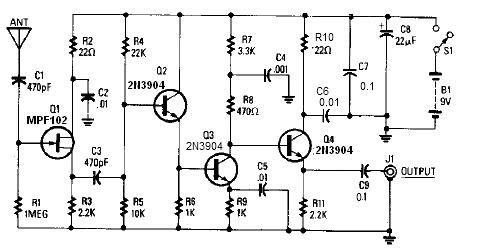
A simple active antenna can be designed using this electronic circuit diagram. This active antenna utilizes transistors and a few common electronic components. In the practice of short-wave frequency reception, a general rule is that a longer antenna will...
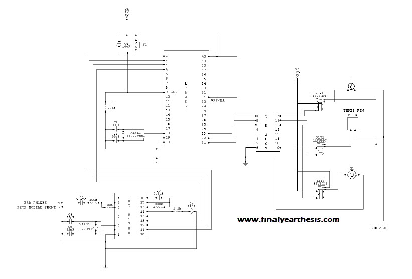
The objective of the project is to create a system that utilizes mobile technology to manage various home appliances based on signals sent from a mobile device. This innovative concept allows for the remote control of appliances through GSM...
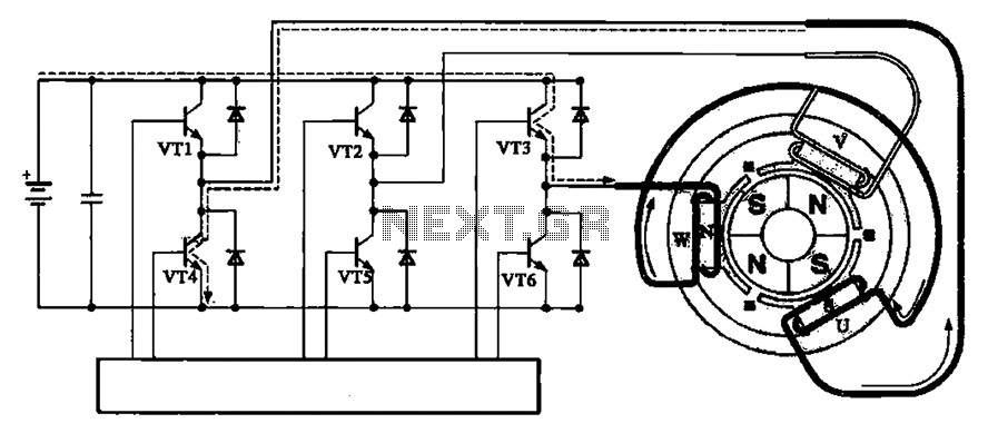
The brushless motor consists of a rotor, a stator, and a drive circuit. The relationship between the brushless motor rotor, stator, and drive circuit is illustrated in the accompanying figure. In the initial state, VT3 and VT4 are conducting,...
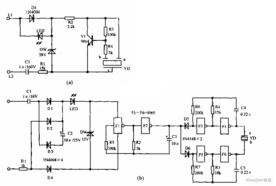
The telephone electronic ringer circuit is illustrated in the provided figure. It features an NPN transistor (either 9014 or 3DG12) as the primary component. The sound device, referred to as YD, functions as both a feedback device and is...
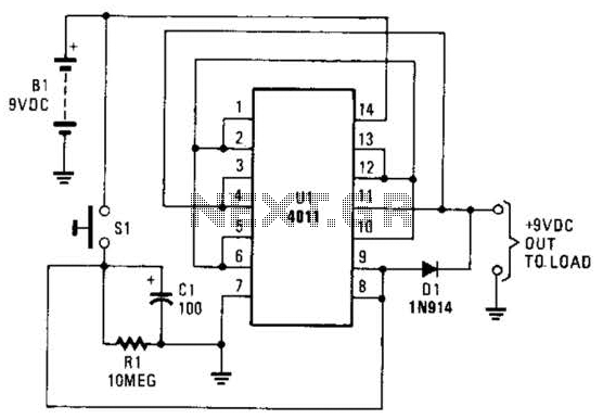
This battery saver circuit can automatically turn off a small piece of test equipment after a desired period of time, allowing for worry-free operation in a workshop environment. The circuit utilizes a CD4011 integrated circuit (IC) to function as...
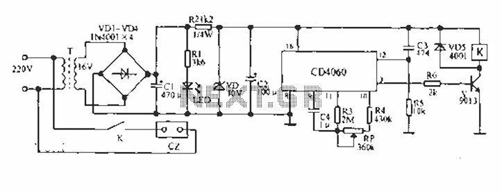
A CD4060 production time controller circuit is illustrated below. It is connected in such a way that R5 and C3 form a differential circuit to create a delay time from the start. Under the influence of the oscillating signal,...
Warning: include(partials/cookie-banner.php): Failed to open stream: Permission denied in /var/www/html/nextgr/view-circuit.php on line 713
Warning: include(): Failed opening 'partials/cookie-banner.php' for inclusion (include_path='.:/usr/share/php') in /var/www/html/nextgr/view-circuit.php on line 713