
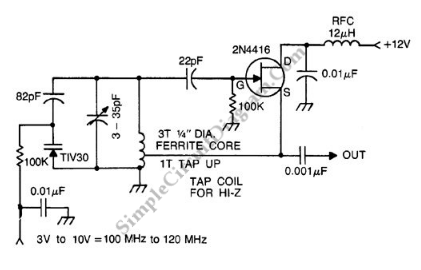
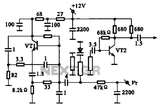
Crystal controlled butler oscillator
The Butler oscillator is a type of electronic oscillator that generates a sinusoidal output signal. It is characterized by its ability to produce stable frequencies across a designated range, making it suitable for various applications in communication systems and signal processing. The oscillator employs a feedback mechanism that is essential for maintaining oscillation.
In the typical configuration, the first stage of the Butler oscillator consists of an active device, such as a FET or a bipolar junction transistor (BJT), which amplifies the input signal. The second stage is crucial for determining the oscillator's performance; therefore, the use of a FET is preferred due to its high input impedance and lower noise characteristics compared to BJTs. The inclusion of a second FET can enhance reliability and performance, especially when the circuit requires consistent oscillation without distortion.
The frequency of oscillation is a function of the LC tank circuit formed by the inductor and capacitor. The resonant frequency (f) can be calculated using the formula:
f = 1 / (2π√(LC))
where L is the inductance in henries and C is the capacitance in farads. By selecting appropriate values for L and C, the desired frequency within the 20-100 MHz range can be achieved. The design must also consider factors such as component tolerances, parasitic capacitances, and inductances, which can affect the overall frequency stability and performance of the oscillator.
In summary, the Butler oscillator is a versatile circuit design that utilizes FETs for improved reliability and performance. The frequency of oscillation is critically dependent on the chosen LC values, making careful selection of these components essential for achieving the desired operational characteristics.A typical Butler oscillator (20-100 MHz) uses an FET in the second stage; the circuit is not reliable with two bipolars. Sometimes two FETs are used Frequency is determined by LC values. 🔗 External reference
Related Circuits
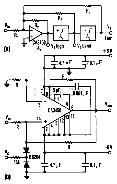
The control voltage Vc effectively adjusts the cutoff frequency w0 of this state-variable filter to any desired value, ranging from approximately 1.7 MHz to 5 MHz, using a BB 204 varicap and a resistance of 100 kΩ. Vc can...
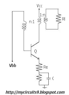
Initially, there is a voltage Vc on capacitor C1 that is greater than Vbb - Vg, where Vg is the cutoff base-emitter voltage and g represents Gamma. Consequently, the transistor is in the off state, and capacitor C1 discharges...

A voltage-controlled oscillator (VCO) operates similarly to a voltage-to-frequency converter (VFC). Its output frequency is determined by a control voltage input. In the circuit diagram, 'd' represents the amplifier input voltage, which is set to 0.6V, while 'h' denotes...
A voltage-controlled oscillator (VCO) is an electronic signal generator that produces a signal with a variable frequency, which is dependent on an input voltage level. A voltage-controlled oscillator is a fundamental component in various electronic applications, including phase-locked loops (PLLs),...
The local oscillator operates at frequencies of 1 GHz or higher, utilizing a common collector circuit, which makes it challenging to generate low-frequency self-oscillation. Typically, the local oscillator signal is passed through a buffer amplifier stage before being applied...

This circuit is designed as a pocket-sized, high-performance audio oscillator. It can operate using a battery-powered version, which is feasible at a very low cost by utilizing a single quad op-amp to provide the entire active circuitry. The design...
Warning: include(partials/cookie-banner.php): Failed to open stream: Permission denied in /var/www/html/nextgr/view-circuit.php on line 713
Warning: include(): Failed opening 'partials/cookie-banner.php' for inclusion (include_path='.:/usr/share/php') in /var/www/html/nextgr/view-circuit.php on line 713