
Arduino Master Reader
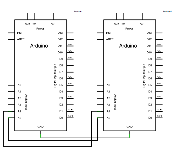
The described circuit employs the I2C protocol, which is a widely used method for inter-device communication in embedded systems. The Master Arduino initiates communication by sending a start condition followed by the address of the Slave Arduino, allowing it to request specific data. The six bytes of data that the Master requests can be any information, such as sensor readings or status updates, depending on the application.
The SCL and SDA lines are critical for this communication. The SCL line is responsible for synchronizing the data transmission, while the SDA line carries the actual data. Pull-up resistors are often recommended on the SDA and SCL lines to ensure that the signals are pulled high when not actively driven low by either device. This helps maintain signal integrity, especially over longer distances or in electrically noisy environments.
Additionally, it is essential to ensure that both Arduino boards share a common ground to avoid potential communication errors due to differing voltage levels. The USB connection to the Master Arduino not only powers the board but also enables serial communication with a computer, allowing for debugging and monitoring of the transmitted data in real-time through the Arduino IDE's serial monitor.
In summary, this configuration exemplifies a simple yet effective method for enabling communication between multiple Arduino boards using the I2C protocol, showcasing the flexibility and scalability of Arduino projects in a variety of applications.In some situations, it can be helpful to set up two (or more!) Arduino boards to share information with each other. In this example, two Arduinos are programmed to communicate with one another in a Master Reader/Slave Sender configuration via the I2C synchronous serial protocol.
Several functions of Arduino`s Wire Library are used to accomplish t his. Arduino 1, the Master, is programmed to request, and then read, 6 bytes of data sent from the uniquely addressed Slave Arduino. Once that message is received, it can then be viewed in the Arduino serial window. The I2C protocol involves using two wires to send and receive data: a serial clock pin (SCL) that the Arduino pulses at a regular interval, and a serial data pin (SDA) over which data is sent between the two devices.
As the clock pulse changes from low to high (known as the rising edge of the clock), a bit of information containing the address of a specific device and a request for data, is transferred from the Arduino to the I2C devices over the SDA line. When the clock pin changes from high to low (the falling edge of the clock), the called upon device transmits it`s data back to the Arduino over the same line.
Because the 12C protocol allows for each enabled device to have it`s own unique address, and as both master and slave devices to take turns communicating over a single line, it is possible for your Arduino to communicate (in turn) with many devices, or other Arduinos, while using just two pins of your microcontroller. Connect pin 4 (the clock, or SCL, pin) and pin 5 (the data, or SDA, pin) on the master Arduino to their counterparts on the slave board.
Make sure that both boards share a common ground. In order to enable serial communication, the master Arduino must be connected to your computer via USB. 🔗 External reference
Related Circuits
Climber A ascends a route while Climber B remains on the ground, tracking Climber A's progress with a laser pointer. The Redpointer device records the exact route taken. In Mode 1, the recorded route is played back in real-time,...
Arduino Event-Driven Universal AV Remote May 1st, 2013. Turn everything on with Airplay. The project involves the development of an Arduino-based universal remote control designed to manage various audio-visual (AV) components through an event-driven architecture. This remote utilizes Airplay...
The text of the Arduino reference is licensed under a Creative Commons Attribution-ShareAlike 3.0 License. Code samples in the reference are released into the public domain. The Arduino platform is an open-source electronics prototyping environment that enables users to create...
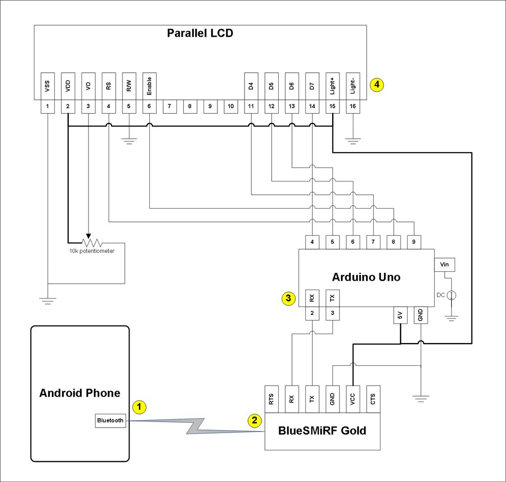
This project involves a modification of the Google Android sample app known as Bluetooth Chat, allowing users to type a message in the Android app and display that same message on an LCD connected to an Arduino Uno. The...
Have you ever wanted your home entertainment or sound system to power on automatically when plugging in your iPod or another portable MP3 player? To achieve automatic power activation of a home entertainment system when a portable device is...
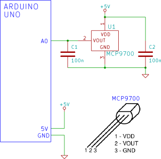
The Arduino reads temperature from an MCP9700 temperature sensor IC and displays the temperature in the Arduino IDE serial monitor window. The circuit utilizes an Arduino microcontroller along with an MCP9700 temperature sensor integrated circuit (IC) to measure ambient temperature....