
Arduino Audio Triggered Power Switch
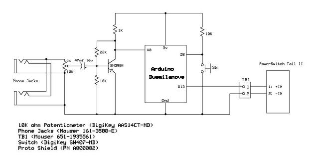
To achieve automatic power activation of a home entertainment system when a portable device is connected, a circuit can be designed that utilizes a combination of a relay and a microcontroller. The microcontroller can be programmed to detect the presence of voltage from the portable device, such as an iPod or MP3 player, when it is plugged in.
The circuit would typically include the following components:
1. **Power Supply**: A regulated power supply to power the microcontroller and other components.
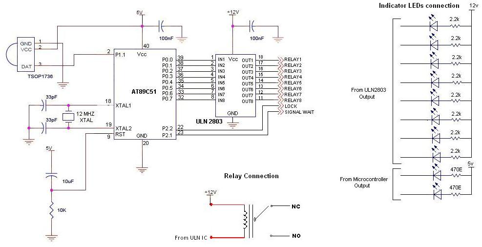
2. **Microcontroller**: A small microcontroller (e.g., Arduino, PIC, or AVR) that monitors the input voltage from the audio device.
3. **Relay Module**: A relay capable of handling the power requirements of the home entertainment system. This relay will be used to switch the power on or off.
4. **Input Connection**: A 3.5mm audio jack or USB connection for the portable device, which will also provide a voltage signal to the microcontroller when the device is connected.
5. **Output Connection**: The relay will be connected to the power line of the home entertainment system, allowing it to control the power state.
The operation of the circuit is as follows: When the portable device is plugged into the input connection, it sends a voltage signal to the microcontroller. The microcontroller, programmed to recognize this signal, activates the relay. Once the relay is activated, it closes the circuit, allowing power to flow to the home entertainment system, thereby turning it on.
In addition, the circuit can be designed to include a delay feature, ensuring that the system does not turn on immediately upon connection, which can prevent potential power surges or damage to the equipment. This can be accomplished by programming the microcontroller to wait a few seconds after detecting the voltage before activating the relay.
This type of circuit can enhance convenience for users, allowing for a seamless integration of portable devices into a home entertainment setup.Ever wanted your home entertainment or sound system to power up itself when plugging in your iPod or other portable MP3 player? Watch this video to s.. 🔗 External reference
Related Circuits
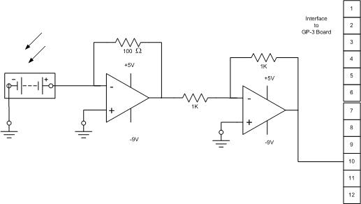
The solar cell used for the solar tracking experiment is made from crystalline silicon, with a maximum voltage rating of 55V and a maximum current rating of 300 mA. It can be purchased at local Radio Shack stores for...
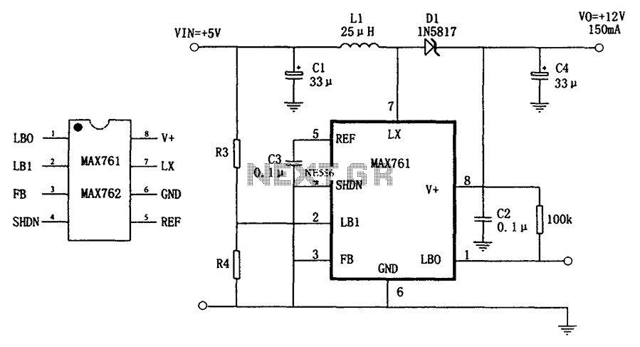
The circuit depicted in the figure illustrates an efficient, low-power step-up DC-DC converter, the MAX761, along with a few external components, which functions as a +5V to +12V boost power supply. Its characteristics include a conversion efficiency of 86%...
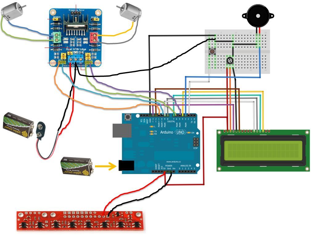
If the robot is positioned on the black line, it will continue moving forward. However, if it veers off the line and enters a white area, it will assess whether to correct its path to the left or right,...
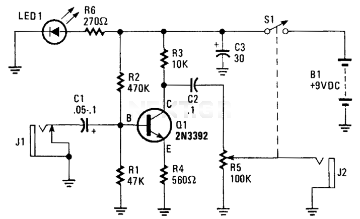
The amplifier's gain is nominally 20 dB. Its frequency response is determined primarily by the values of a few components, mainly C1 and R1. The schematic diagram values provide a response of ±3.0 dB from approximately 120 Hz to...
To control multiple switches, it is necessary to transmit several bits via infrared (IR) transmission to indicate which key is pressed on the remote control and, consequently, which switch on the switchboard to operate. This project utilizes a commercially...
This is a simple yet reliable device based on one of the oldest integrated voltage regulators, the LM723. The LM723 is a versatile voltage regulator that can be configured to provide a wide range of output voltages. It is capable...
Warning: include(partials/cookie-banner.php): Failed to open stream: Permission denied in /var/www/html/nextgr/view-circuit.php on line 713
Warning: include(): Failed opening 'partials/cookie-banner.php' for inclusion (include_path='.:/usr/share/php') in /var/www/html/nextgr/view-circuit.php on line 713