
Arduino Motor Knob
Stepper motors are widely utilized in applications requiring precise positioning and control, such as 3D printers, CNC machines, and robotics. The operation of a stepper motor is based on the principle of electromagnetic induction, where the coils create magnetic fields that interact with the permanent magnets on the rotor. When the coils are energized in a specific sequence, the rotor aligns itself with the magnetic field, resulting in incremental movement.
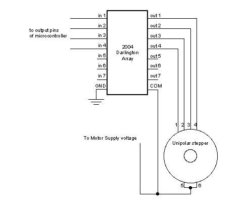
The two primary types of stepper motors differ in their construction and operation. Unipolar stepper motors have a center-tapped winding for each phase, allowing for simpler control but typically resulting in lower torque compared to bipolar motors. Bipolar stepper motors, on the other hand, utilize a more complex winding arrangement, allowing for higher torque and efficiency but requiring more intricate control circuitry.
The circuit design for controlling stepper motors involves connecting the motor coils to a microcontroller, such as an Arduino. The microcontroller sends signals through designated digital pins, which energize the coils in the correct sequence to achieve the desired movement. In the provided example, pins 8, 9, 10, and 11 are utilized for this purpose. The potentiometer connected to analog input 0 serves as a variable resistor, allowing the user to adjust the speed and direction of the motor by altering the input voltage.
To implement this control system, careful attention must be paid to the power requirements and specifications of the stepper motor in use. Proper power supply and driver circuits are essential to ensure reliable operation and prevent damage to the motor or control circuitry. Additionally, understanding the step angle of the motor is crucial for achieving the desired resolution in positioning.
Overall, the integration of stepper motors with microcontrollers provides a powerful solution for applications requiring precise control of movement, making them an essential component in modern electronic designs.Stepper motors, due to their unique design, can be controlled to a high degree of accuracy without any feedback mechanisms. The shaft of a stepper, mounted with a series of magnets, is controlled by a series of electromagnetic coils that are charged positively and negatively in a specific sequence, precisely moving it forward or backward in small
"steps". There are two types of steppers, Unipolars and Bipolars, and it is very important to know which type you are working with. For each of the motors, there is a different circuit. The example code will control both kinds of motors. See the unipolar and bipolar motor schematics for information on how to wire up your motor. In this example, a potentiometer (or other sensor) on analog input 0 is used to control the movement of a stepper motor using the Arduino Stepper Library.
The stepper is controlled by with digital pins 8, 9, 10, and 11 for either unipolar or bipolar motors. 🔗 External reference
Related Circuits

The SN754410 Dual Motor Control circuit is illustrated below. It is straightforward in design, with the PIC serving as the central processor. The main components included in the schematic are the 7805 voltage regulator, the 18F452 microcontroller, and the...
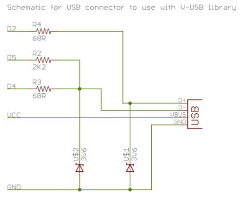
To successfully complete this project, it is necessary to construct the circuit as illustrated or as previously demonstrated. While the construction process is straightforward, any errors may prevent the V-USB software from functioning properly, potentially resulting in project failure....
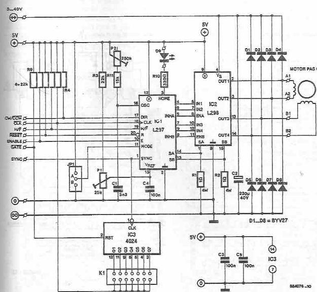
The L297 and L298 integrated circuits manufactured by SGS Thomson (ST) can be utilized to create a control circuit for a stepper motor, accommodating both two-phase bipolar and unipolar four-phase configurations, with a maximum current rating of 2 A...
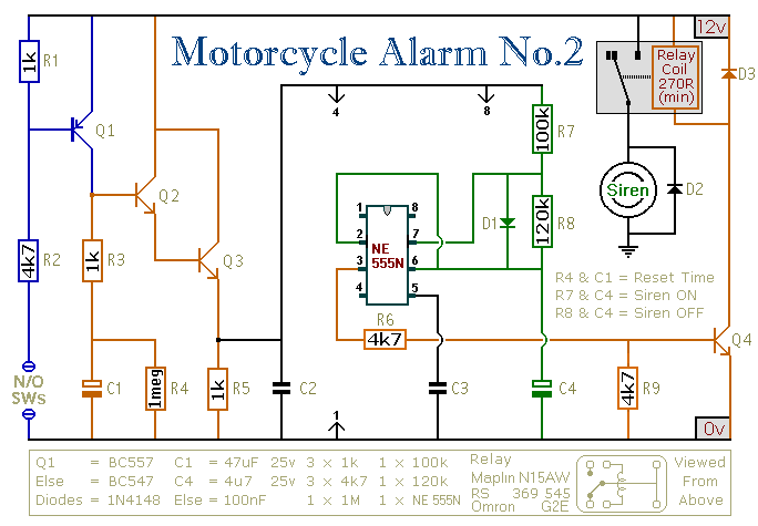
This circuit provides an intermittent siren output with an automatic reset function. It can be manually activated using a key switch or a concealed switch, and it can also be configured to engage automatically when the ignition is turned...
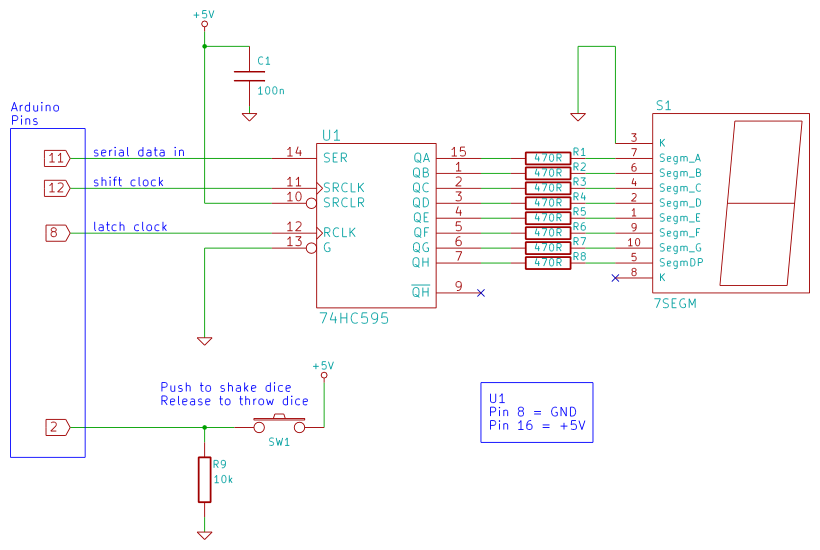
Arduino 7-segment display dice circuit and tutorial with Arduino sketch. Build a dice that is shaken by holding a button in and thrown by releasing the button. The shake, throw, and number thrown are animated and displayed on a...
This circuit can control a small DC motor, like the one in a tape recorder. When both the points A & B are "HIGH" Q1 and Q2 are in saturation. Hence the bases of Q3 to Q6 are grounded....