
SN754410 Dual Motor Control Circuit

The SN754410 Dual Motor Control circuit operates effectively for applications requiring precise motor control. The circuit design incorporates a robust structure that allows for the simultaneous control of two DC motors or one stepper motor through the use of H-bridge configurations. The LM7805 voltage regulator ensures that the microcontroller and motor driver receive a stable +5V supply, which is crucial for reliable operation.
In this circuit, the PIC 18F452 microcontroller plays a vital role, as it processes analog signals from the sensors or user inputs and translates them into digital signals that control the motor operations. The use of PORTA pins for analog inputs allows for the integration of various sensors, enabling the system to respond to external conditions. The output pins on PORTD are strategically assigned to control the motor driver, facilitating precise control over motor speed and direction.
The SN754410 motor driver is designed to handle the necessary current for the motors while providing features such as braking and direction control. The enable pins ensure that the H-bridges are always active, but they can also be modified for dynamic control through the microcontroller if desired. This flexibility allows for advanced control strategies, such as PWM (Pulse Width Modulation) for speed regulation.
Overall, this circuit exemplifies a practical approach to motor control, combining simplicity with functionality. It is suitable for various robotics and automation projects where precise motor control is essential.The SN754410 Dual Motor Control circuit can be seen below. It is just about as simple as it looks with the PIC being the central processor. The main parts used and seen in the schematic below are the 7805, 18F452 and SN754410. The LM7805 +5v Regulator is used for its simplicity and the fact that the PIC uses the +5v digital standard. Since our motors are not too current demanding, this regulated supply will also be connected to the motor controller. The PIC 18F452 acts as the primary input and output control unit. It will be taking the analog input from PORTA pins 2 (RA0) and 3 (RA1), evaulating this input and then using PORTD, pins 19, 20, 21 and 22 to tell the motor controller what motors to move where and how fast.
The Motor Controller has 4 input pins 1A, 2A, 3A and 4A. The corresponding output pin for each half-h-bridge is marked with a Y (i. e. 2Y). The digital supply will be used for both signal and motor control so Vcc1 and Vcc2 are tied to the +5v regulated power. Finally, two Enable pins (pin 1 and pin 16) are connected to +5v through a 10k © resistor so these h-bridges are always enabled.
You could alternatively connect this to an I/O pin on the PIC to control these enable bits, but for simplicity I have not done that here. 🔗 External reference
Related Circuits
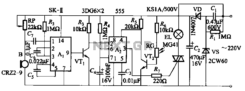
This circuit utilizes a dedicated voice integrated circuit (AI) of the SK type, which incorporates an internal bistable multivibrator and three inverting amplifiers. The 555 integrated circuit (IC) A2 is employed for delay control. The described circuit is designed to...

This circuit displays a sound generator that simulates the siren of a British police car. The circuit is constructed using two timer IC 555. The sound generator circuit designed to simulate a British police car siren utilizes two 555 timer...

The touch sensor switch circuit diagram features a step-down rectifier circuit, a 555 timer, and flip-flops. When a hand touches the metal sheet A, the sensor signal activates the internal comparator of the 555 timer, setting the output to...

A dimming control circuit is implemented using a single-chip I/O port sinking method to control a thyristor switch for dimming functionality. The MOC3041 optocoupler features an internal zero-crossing detection circuit, allowing for effective control of the thyristor. This design...
A simple electronic lock circuit that requires minimal materials for its construction. This electronic lock circuit is designed for ease of assembly and functionality, making it suitable for various applications where secure access control is necessary. The circuit typically comprises...
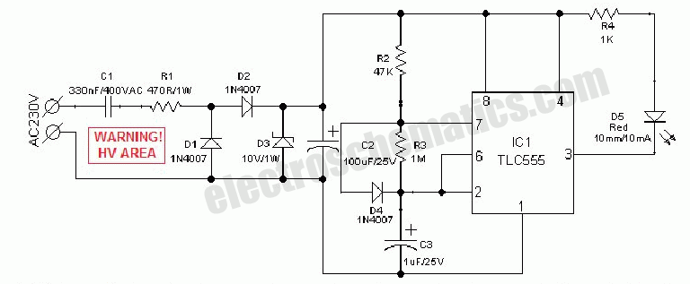
An AC mains operated single LED flasher circuit is constructed using the widely utilized CMOS timer chip TLC555. The entire circuit is powered directly from the 230VAC grid supply via a capacitive potential divider and associated components. This compact...