
Arduino V-USB / HID 14 channel data logger
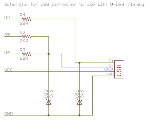
The project involves creating a USB interface circuit using the V-USB software, which is designed to enable microcontrollers to communicate over USB without the need for a dedicated USB controller. The circuit typically includes components such as a microcontroller, resistors, capacitors, and a diode.
To ensure successful operation, it is essential to follow the schematic layout closely, as any deviation could lead to malfunction. The microcontroller should be configured correctly, with appropriate firmware uploaded to support USB communication. Resistors must be selected based on the specifications provided in the schematic to ensure proper voltage levels and signal integrity.
The diode serves as a protective component, preventing reverse polarity that could damage the circuit. It is critical to install the diode in the correct orientation, as reversing it can lead to circuit failure. Cold solder joints must be avoided by ensuring that all connections are made with sufficient heat and solder to create reliable electrical connections.
Testing the circuit before connecting it to a PC is vital. This can be achieved by using a multimeter to verify voltage levels and continuity of connections. Additionally, a test load can be connected to simulate the USB device's operation and ensure that the circuit behaves as expected.
In summary, careful construction, thorough testing, and adherence to the schematic are imperative for the successful implementation of this USB interface project. Failure to do so may result in significant damage to the PC and the circuit itself, highlighting the importance of precision and caution in electronic assembly.To be successful with this project, you will need to construct this circuit in some manner, either as shown here or as I showed in the previous section. While the construction is not complicated, errors will keep the V-USB software from working (said another way, the project will be a BIG flop and will not work.
) Additionally, if you have a wiring accident, diode reversed, improper parts selection, or cold solder joints, the circuit is likely to not work. AT WORST, IMPROPER CONSTRUCTION AND WIRING COULD DAMAGE YOUR PC USB PORT, SYSTEMBOARD, OR CREATE OTHER SERIOUS AND EXPENSIVE DAMAGE.
DO NOT ATTEMPT TO BUILD THIS INTERFACE AND USE IT ON YOUR PC UNLESS YOU ARE CONFIDENT YOU CAN CONSTRUCT THE CIRCUIT PROPERLY AND HAVE THE ABILITY TO TEST YOUR INTERFACE BEFORE CONNECTING TO YOUR PC. IF YOU MOVE FORWARD WITH CONNECTING TO YOUR PC YOU ASSUME ALL RISKS ASSOCIATED WITH THIS PROJECT. 🔗 External reference
Related Circuits
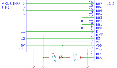
This tutorial demonstrates how to connect an LCD display to an Arduino and test it. It provides a step-by-step guide for beginners on using a breadboard to establish the connection. To connect an LCD display to an Arduino, first gather...
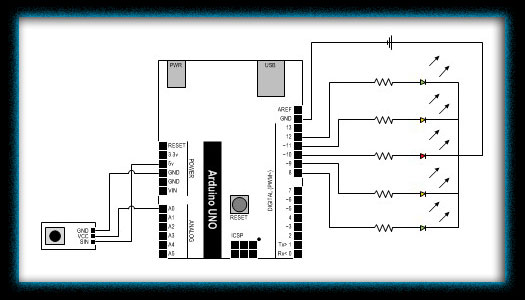
Finally, an Arduino Uno Open Source Prototyping Platform has been purchased, and the first impressions are noteworthy. The Arduino Uno is a widely used microcontroller board based on the ATmega328P microcontroller. It features 14 digital input/output pins, six analog inputs,...
The Arduino is a user-friendly and versatile controller platform suitable for various projects. Recently, an Ethernet shield was purchased for the Arduino to enable remote control of projects, which proved to be highly effective. This led to the idea...
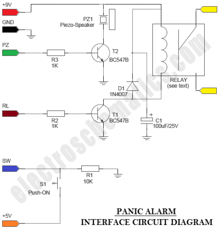
The circuit is an Arduino-based Panic Alarm. The wiring is straightforward, enabling even novices to construct this interesting circuit with ease. Arduino is a family of microcontrollers and a software environment (Arduino IDE) that facilitates the creation of programs,...
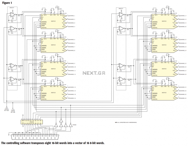
The circuit in Figure 1 controls 32 voltage-output channels from the parallel port of a PC. The circuit comprises eight DAC7615 quad voltage-output, serial-data programmable, 12-bit DACs. The controlling PC individually programs each of the 32 DAC channels, and...
A clock-and-data recovery (CDR) circuit is utilized to recover the clock from a transmitted data stream and re-time that data with the recovered clock. These circuits are generally positioned at the front-end of receiver chips to extract the clock...
Warning: include(partials/cookie-banner.php): Failed to open stream: Permission denied in /var/www/html/nextgr/view-circuit.php on line 713
Warning: include(): Failed opening 'partials/cookie-banner.php' for inclusion (include_path='.:/usr/share/php') in /var/www/html/nextgr/view-circuit.php on line 713