
Arduino Punk Console
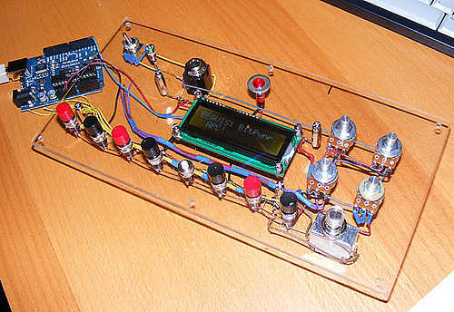
The circuit design for the programmable 8 step tone sequencer based on an Arduino microcontroller incorporates several key components that work together to produce a series of tones in a sequenced manner. The primary component is the Arduino microcontroller, which serves as the brain of the operation, controlling the timing and output of the tones.
The sequencer is designed to allow user programming of up to 8 distinct steps, with each step capable of defining a specific tone frequency and duration. The Arduino can be programmed using the Arduino IDE, allowing for easy modifications and updates to the tone sequences.
An essential feature of this circuit is the inclusion of a 2 line x 16 character backlit LCD display. This display provides a user interface for programming the sequencer, allowing users to view and edit the sequence parameters such as tone frequency, duration, and the overall sequence length. The LCD is connected to the Arduino via an I2C interface, which simplifies wiring and reduces the number of required pins.
In addition to the microcontroller and LCD, the circuit includes a piezo buzzer or speaker, which serves as the output device for the generated tones. The audio output can be amplified using a simple transistor amplifier circuit, ensuring that the tones are audible even in noisy environments.
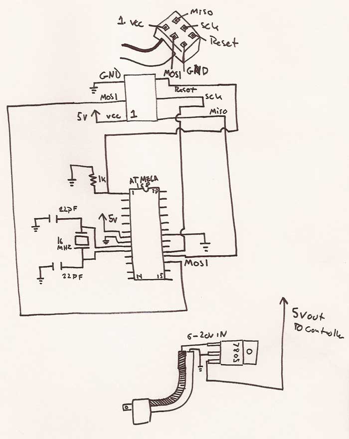
Powering the circuit can be achieved through a standard USB connection or an external power supply, depending on the application requirements. Proper voltage regulation and decoupling capacitors should be included to ensure stable operation of the microcontroller and other components.
Overall, this programmable 8 step tone sequencer offers a versatile platform for creating sound sequences, suitable for applications in music, alerts, or other audio signaling needs.A programmable 8 step tone sequencer using an Arduino microcontroller. Features a 2 line x 16 character backlit LCD display 🔗 External reference
Related Circuits
The Arduino library can be utilized with other Integrated Development Environments (IDEs) to enhance code organization, particularly for extensive projects. This approach facilitates the integration of code not specifically designed for Arduino and serves as a pathway to more...
After completing the prototype and ensuring the sketch functions correctly, it is time to construct the circuit. The aim is not to provide a detailed explanation of how to create printed circuit boards, but rather to offer a general...
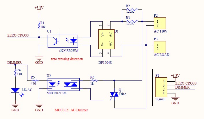
Have you verified whether you can see the zero crossings on your input pin? It may be beneficial to write a sketch that toggles the LED on pin 13 every 50 or 60 zero crossings. This should result in...
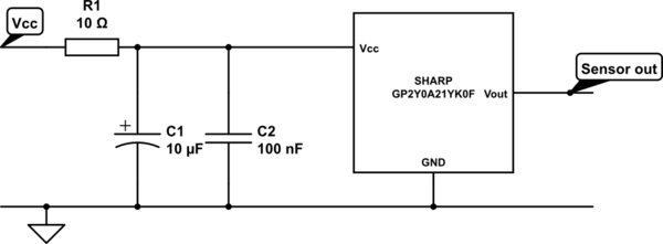
A project involves two distance sensors that signal an Arduino to operate a servo motor when an object comes within range. The system functions correctly; however, the sensors output a consistently high voltage, necessitating a high cutoff voltage in...
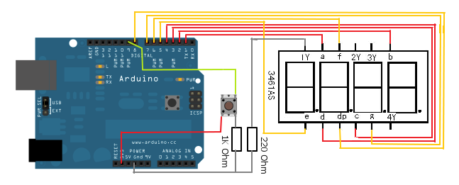
The 7-segment LED display is a highly useful component, yet it can be quite confusing and challenging for beginners to use. However, it becomes straightforward once it is operational for the first time. The display consists of seven LEDs,...
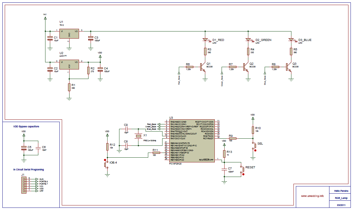
The Circuit is composed of two sections, the light sensing and the power switching. The light sensing part consists of a photo-resistor R4, connected like a voltage divider to R2. Since the resistance of the photo-resistor changes depending on...