
microcontroller Arduino 230v Light bulb dimming
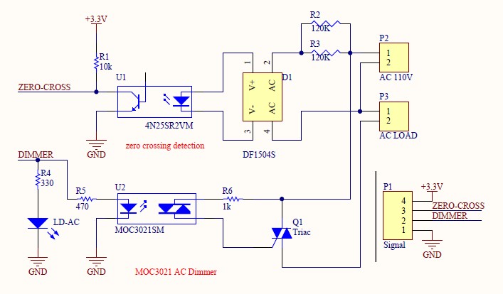
To observe zero crossings effectively on an input pin, it is essential to ensure that the setup is configured correctly. A zero crossing detector typically involves a comparator circuit that outputs a high signal when the input AC voltage crosses zero volts. This output can be connected to a digital input pin on the Arduino.
The suggested approach of toggling the LED on pin 13 can be implemented by writing an Arduino sketch that utilizes an interrupt service routine (ISR). The ISR should be triggered on the rising edge of the signal from the zero crossing detector. This will allow for precise timing, ensuring that the LED toggles at a frequency corresponding to the zero crossings detected.
In the sketch, the setup function should configure the pin connected to the zero crossing detector as an input and enable the appropriate interrupt. The loop function can remain empty or perform other tasks, as the LED toggling will be handled by the ISR. The timing of the toggling can be adjusted by counting the number of zero crossings detected, allowing for flexibility in the observed blink rate.
It is crucial to verify the type of Arduino board being used, as different models may have varying interrupt capabilities and pin configurations. This information will help ensure that the correct pins are utilized and that the code is compatible with the specific board's architecture.Did you check if you actually see the zero crossings on your input pin You might want to write a sketch that toggles the pin13 LED every 50 or 60 or zerocrossings. You should see a visible 1Hz blink. jippie Mar 3 `13 at 11:41 Which input pin did you use for attaching the zero crossing detector Notice that interrupt number may not be the same as input pin number and may interrupt pin numbers
may vary across Arduino board type. So which Arduino are you using jippie Mar 3 `13 at 11:44 @jippie i am new to this can you help me with it "Did you check if you actually see the zero crossings on your input pin You might want to write a sketch that toggles the pin13 LED every 50 or 60 or zerocrossings. " Daniel Euchar Mar 3 `13 at 11:49 🔗 External reference
Related Circuits
1995 Nissan Altima Brake and Tail Light Wiring Diagram. The wiring diagram for the brake and tail lights of the 1995 Nissan Altima provides a visual representation of the electrical connections and components involved in the lighting system. This diagram...
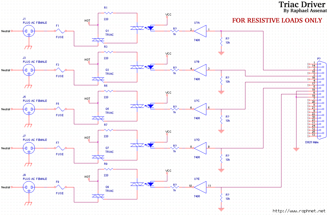
Controlling room lighting using a computer. Triacs and opto-couplers have been purchased for this purpose. A schematic was drawn and a prototype was built, which functioned correctly. Although not visible in the pictures, there is a cable extending from...
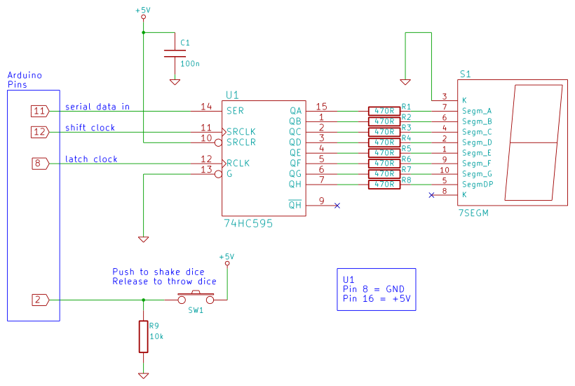
Arduino 7-segment display dice circuit and tutorial with Arduino sketch. Build a dice that is shaken by holding a button in and thrown by releasing the button. The shake, throw, and number thrown are animated and displayed on a...

The following circuit illustrates an Automatic Light Dimmer Circuit Diagram utilizing a 1N4007 diode. Features include integration within a wall-mounted box. The Automatic Light Dimmer Circuit is designed to adjust the brightness of a light source automatically based on ambient...
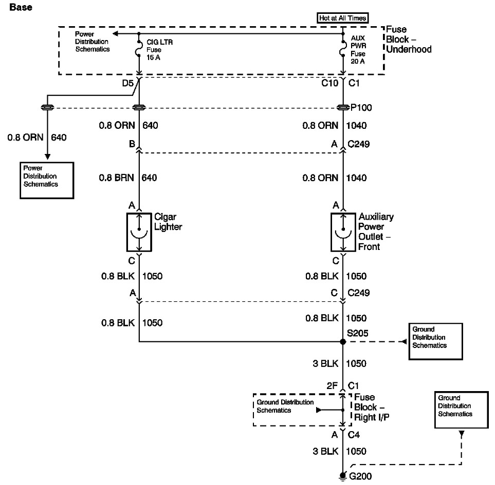
The provided information includes a fuse block diagram with the Auxiliary Power (Aux Pwr) fuse highlighted. It is advisable to check both sides of the fuse using a test light or multimeter to ensure functionality. It is assumed that...
This simple electronics timing light uses an RC circuit as a delay-off timer to control an incandescent lamp via a relay. The described timing light circuit employs a resistor-capacitor (RC) network to create a time delay that governs the operation...