
Learn how to use 7-Segment LED Display using Arduino

The 7-segment LED display is a crucial component in various electronic applications, particularly in digital clocks, counters, and other numeric displays. Each of the seven segments can be illuminated in different combinations to represent the digits from 0 to 9, as well as some alphabetical characters. The display can be categorized into two types: Common Cathode and Common Anode. In a Common Cathode configuration, the cathodes of all segments are connected to ground, while each segment's anode is connected to an individual control pin. Conversely, in a Common Anode display, all anodes are connected to a positive voltage, and the segments are turned on by connecting their cathodes to ground.
To interface a 7-segment display with an Arduino, each segment must be connected to a digital output pin. For example, segment 'a' can be connected to pin 2, segment 'b' to pin 3, and so on, with the decimal point segment connected to another pin if needed. The ground pin of the display should be connected to the Arduino's ground.
The programming aspect involves defining a function that controls which segments light up to form the desired number. This can be achieved using arrays to map the segment states for each digit. A typical implementation includes a function that takes a digit as input and activates the corresponding segments by setting the appropriate pins HIGH or LOW.
To enhance the functionality, the created class can be expanded with additional methods, such as displaying characters, scrolling numbers, or even handling multiple displays. This modular approach allows for greater flexibility and customization, facilitating the integration of the 7-segment display into various projects.7-Segment LED Display is a very useful component, but also a very confusing and difficult piece to use for beginners. It won`t be difficult once you get it working for the first time. It basically consists of 7 LEDs, (8 if include decimal point). Just like controlling a single LED, we need to connect each segment LED` to a Arduino digital pin. Here is the circuit diagram of the LED display: You might notice, there are 2 different type of them, don`t be scared by them, because in the market, the Common Cathode type is the most popular so you won`t need to care about the other type. Basically, all you need to do is to connect each LED with a pin, and connect the shared Gnd connector to the ground pin.
Next you will need to program it, sorequired LEDs are switched on todisplay different number. I have created a class for using the 7 seg LED display, it`s not a complete working class, but gives a few very useful basic functions. Feel free to expand it and add new useful functions, or create your own class. 🔗 External reference
Related Circuits
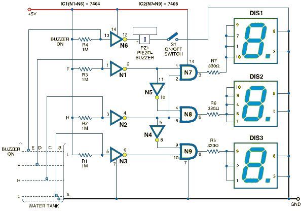
This schematic outlines a straightforward electronic project for designing a water level indicator circuit. It employs a 7-segment display to represent water levels in a tank as low, half, and full, indicated by the letters L, H, and F,...
A function generator that operates within a frequency range of 0.1 Hz to 20 MHz can be easily constructed using the MAX038 integrated circuit chip. This describes a straightforward implementation of the device. The MAX038 is a precision waveform generator...
In this figure, S1 initiates the timing process, and once the timer is activated, toggling this switch will not impact the timing operation. S2 serves as the OFF switch located in the center; toggling this switch allows the timer...
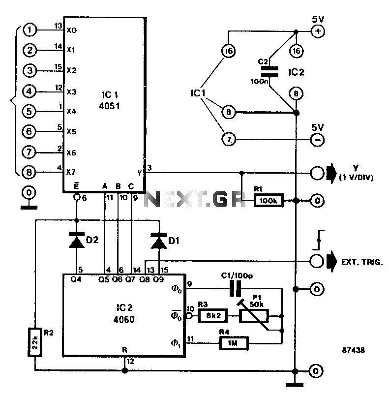
This circuit transforms a standard oscilloscope into a multifunctional eight-channel display for direct voltage measurements. The trends of each of the eight input levels can be easily monitored, although the achievable resolution is limited. The circuit diagram features an...
This circuit diagram represents a microphone preamplifier, specifically designed to prioritize voice signals over other audio inputs. In its basic configuration, the circuit includes a microphone unit and a change-over switch that connects to an amplifier. When the push-to-talk...
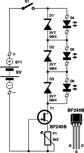
These small electronic lamps are quite practical and have a long lifespan. Approximately 40 years after Nick Holonyak invented the first LED, they have become nearly essential. Any dedicated electronics enthusiast typically keeps a few in their collection. Prior...