
Arduino RFID Door Lock
The RFID door lock system utilizes an Arduino-based microcontroller to manage access control through an RFID reader. The selected ATMega 168 microcontroller is capable of handling the input from the RFID module and controlling the output to the door lock mechanism. The design includes a voltage regulator (7805) to ensure stable operation of the microcontroller and connected components by providing a constant 5V supply.
The RGB LED is employed to provide visual feedback for the system's status, indicating whether access is granted (green), denied (red), or in a standby state (blue). The TIP31A transistor is utilized to switch the higher voltage required for the door lock, allowing the Arduino to control the lock without directly handling high current loads.
The ID-20 RFID reader communicates with the Arduino via a serial connection, transmitting the unique identifiers of RFID tags presented to it. The design includes a robust breadboarding approach, allowing for easy modification and testing of the circuit before finalizing the custom PCB layout. The breakout board for the ID-10/ID-20 simplifies connections, ensuring reliable operation and ease of integration into the overall system.
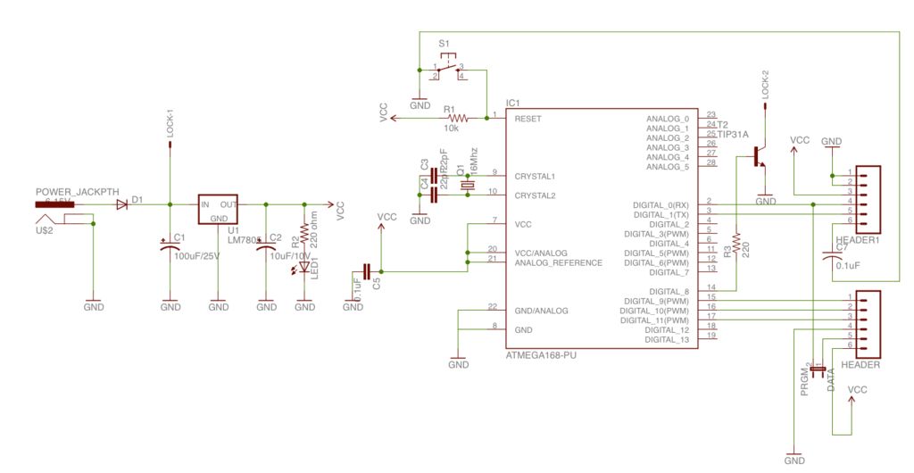
In summary, this RFID door lock project combines essential electronic components and programming to create a secure and efficient access control system. The thoughtful arrangement of hardware and software components allows for a compact design while maintaining functionality and security.The first step to building a RFID door lock with a basic Arduino is to bread board out a basic working arduino. Most Arduino pre-flashed ATMega 168 chips come with the default blink program pre installed. Connect a LED to digital output 13 and verify that everything is working. The hardware portion of this RFID reader would be too simple if we use d a regular arduino with built in USB programmer. Since Iplan on putting this into the wall and not touching it again Idont want to use a big bulky $30 arduino board when I can buy a $5 ATMega 168 and make a much smaller custom PCB. Because Ichose to make a basic Arduino circuit myself Ineed an external USB->Serial FDIT programmer. Ihave included Eagle schematics of the controller with a power supply built from a 7805 voltage regulator.
In testing Iused a bread board power supply. To get an arduino up and running all you really need is the ATMega168 with the arduino software flashed on it, 2x 22pF capacitors, 16mhz crystal, 10k ohm resistor, push button and a breadboard. The hookup for this is well known but Ihave included the entire schematic for the circuit. The arduino is going to trigger 4 outputs, 1 each for Red/Green/Blue LEDs, and 1 to trigger the TIP31A to send 12vDC to the door lock.
The arduino receives serial data in on its Rx line from the ID-20 RFID reader. Now that you have your arduino bread boarded and working you can put together the RFIDreader portion of the circuit that will contain the ID-10 or ID-20 and RGB LED to indicate the status of the circuit. Remember that the reader will be outside and separate from the controller inside so that someone cannot easily break in.
To build this, we are going to send 5v/Ground over from the primary bread board to a secondary bread board we are building the Reader on. Also send over 3 wires from 3 of the arduino output pins to control the RGB LED, one for each color. One more wire, Brown in the pictures, will be a serial connection for the ID-20 to talk to the arduino`s Rx serial input.
This is a very simple circuit to connect. LED`s get resistors and a few points on the ID-20 are tied to ground/5v to set the correct status. To make it easier to breadboard the ID-10/ID-20 Sparkfun sells a Breakout board that allows you to attach longer pin headers that are spaced to fit a bread board. This part and the pinheaders and listed in the parts list. 🔗 External reference
Related Circuits
This is a simple automatic light switch circuit designed for bedrooms. After construction, the input terminals of this circuit should be connected in parallel to the intended lighting fixture. The automatic light switch circuit utilizes a light-dependent resistor (LDR) as...
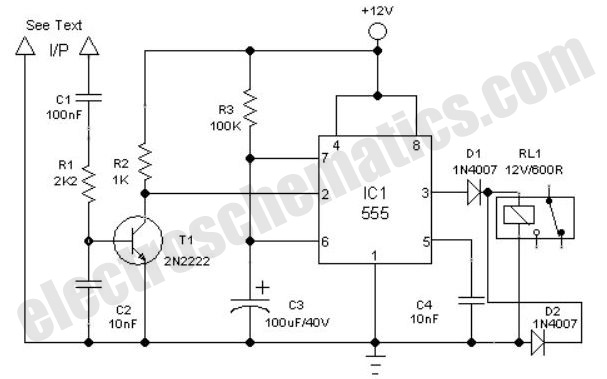
The digital lock shown below uses 4 common logic ICs to allow controlling a relay by entering a 4 digit number on a keypad. The first 4 outputs from the CD4017 decade counter (pins 3,2,4,7) are gated together with...
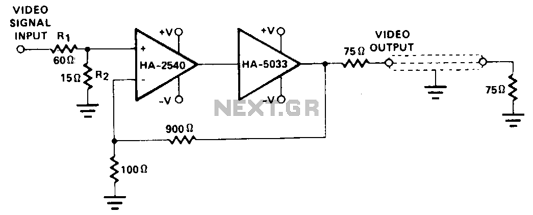
This configuration employs the wide bandwidth and high speed of the HA-2540, in conjunction with the output capabilities of the HA-5033. Stabilization circuitry is not implemented, as the HA-2540 operates at a closed-loop gain of 10 while maintaining an...
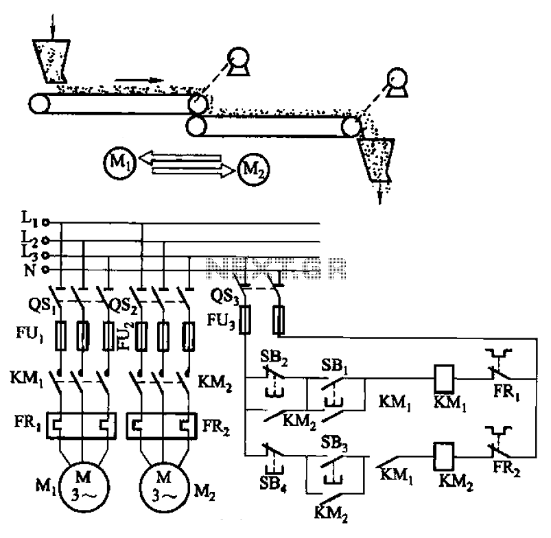
The circuit depicted in Figure 3-86 utilizes a line utilization time relay to control two motors, starting one before the other after an initial stall. The time relay KTi can be adjusted to modify the starting interval of the...
A single beautiful giant ZM1042 NIXIE tube was acquired from Jim Oostveen, leading to the idea of constructing a single-digit NIXIE clock for Geert. The ideal case for this clock was found at a local IKEA store: a wooden...
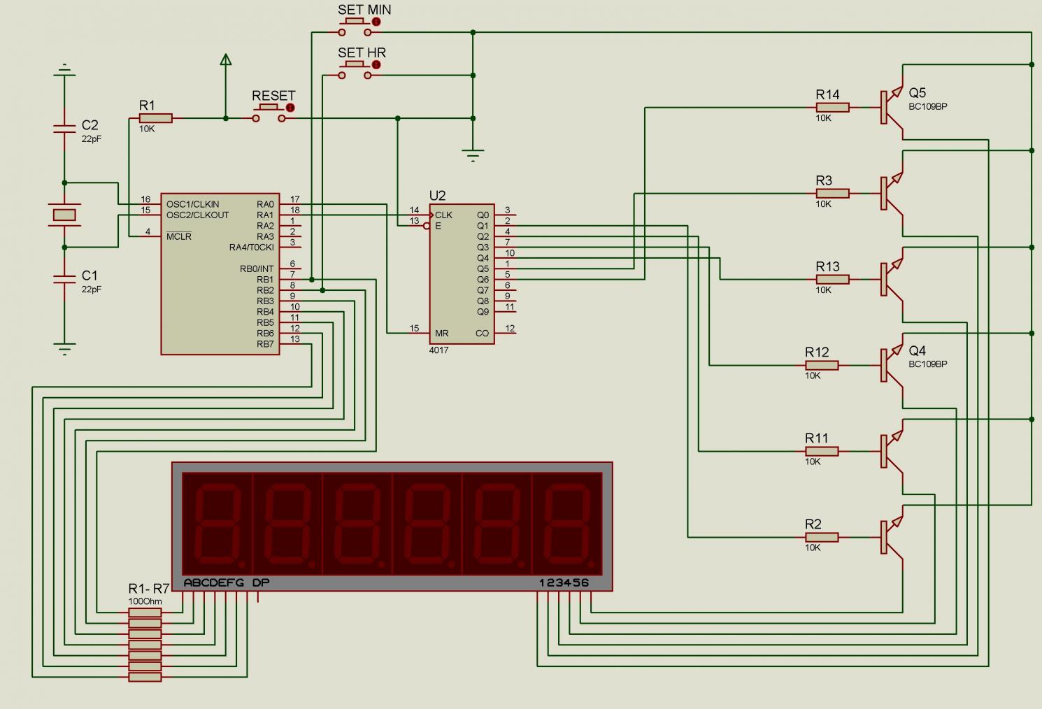
There are issues with simulating this circuit on Proteus. Please review it to ensure no errors were made. The user is also a novice. The circuit simulation in Proteus can often present challenges, especially for those who are new to...
Warning: include(partials/cookie-banner.php): Failed to open stream: Permission denied in /var/www/html/nextgr/view-circuit.php on line 713
Warning: include(): Failed opening 'partials/cookie-banner.php' for inclusion (include_path='.:/usr/share/php') in /var/www/html/nextgr/view-circuit.php on line 713