
RGB LED Strip Circuit with Arduino

The circuit schematic will include the following components: an Arduino microcontroller, a transistor (such as a MOSFET) for controlling the LED strip, a heatsink for the transistor, a 7805 voltage regulator for providing a stable 5V supply to the microcontroller, and the RGB LED strip itself. The Arduino will be programmed to generate PWM signals that modulate the brightness of each color channel (red, green, and blue) of the LED strip. The transistor will act as a switch, allowing the higher voltage (9-12V) from the power supply to drive the LED strip while being controlled by the low-voltage signals from the Arduino.
Connections will be made as follows: the Arduino's PWM output pins will connect to the gate of the transistor, while the source will connect to ground. The drain will connect to the negative side of the LED strip, with the positive side connected to the external power supply. The 7805 voltage regulator will be connected to the power supply to ensure a constant 5V output to the Arduino. The heatsink will be mounted on the transistor to dissipate heat generated during operation, ensuring reliable performance. Proper attention to component ratings and thermal management will lead to a successful and efficient PWM control system for the RGB LED strip.This Instructable covers the assembly of a circuit capable of PWM-ing ( pulse width modulating ) a high-power RGB LED strip and programming an Arduino to cycle through a range of colors. In this context, high power is 9-12 volts. I will discuss how to mount a transistor to a heatsink and assemble the circuit. I will not go into soldering as som e of the RGB LED strip comes with leads (and there is no shortage of great tutorials out there). Also, I will use the most plain, non-jargony language possible to explain the circuit because I know how frustrating it can be to learn this stuff. If you are new to Arduino and are wondering why more than a few LEDs or other components like motors won`t activate when functions are called in the code, its because each output has a current limit of 40mA.
In other words, a component cannot draw more than 40mA of current from each channel. To refer to the water analogy of electronics, the pump pressure is 5V, and the amount of water is the number of electrons (measured in Amps, or in our case, a much smaller amount milliamps, mA). To accommodate a load that requires more current than 40mA at 5V, we will use our microcontroller to control a transistor, which will provide a component with power from an external source (the battery).
Without getting too technical, its worth knowing that individual strips are made up of 3 LEDs in series which can be cut with clippers at any junction. If you want to cut the strip at any point, just be sure to leave connection points on each halve. To understand how the RGB LED strip can be powered with 9-12V, you need to know the difference between circuits in series vs.
parallel (this page has a simple explanation with great illustrations, and there is a popular Instructable that covers wiring LEDs in series & parallel ). Basically, when LED`s are connected in series, the supply voltages and necessary current are added together (respectively).
For example, since an average RGB LED requires 3. 3 V and 60mA (at full brightness; each color channel draws 20mA, so R-G-B all on at same time is 20 x 3 = 60mA), each strip of 3 RGB LEDs will require approximately 9. 9V ( the strip I`m using from Jameco can be powered between 9-12V. Be sure to look at your product`s datasheet to prevent frying your components. Not all RGB LED strip is powered in the 9-12V range, such as Adafruit`s digitally addressable RGB LED strip ).
One more thing, these strips are common anode, meaning the LEDs share a positive terminal ( read about anode vs. cathode ). Perhaps the greatest take-away is the power limitation of the Arduino. The next section which shows how to use a transistor can be applied to all sorts of other components (ex.
motors, solenoids, servos) that require more than 40mA at 5V. A heat sink s function is to dissipate heat so components don`t fry, melt connections/become un-soldered, or become too hot to touch. This is really important if you`re using a 7805 for voltage regulation, which I`m also doing in this circuit.
The 7805 will output a steady 5V to the microcontroller and dissipate quite a bit of heat. I like to do this because I don`t trust the Arduino SMD voltage regulator, especially on ProMinis which I use frequently (even thought the Arduino Uno datasheet says the input voltage can be as high as 20V). This part is pretty straight-forward. Apply some heat sink compound to the transistor (first image in this series) and then put the nylon washer on screw on then through the transistor (second).
The compound increases thermal conductivity, which aids in the dissipation process. Lastly, fasten the nut to the back of the heat sink. 🔗 External reference
Related Circuits
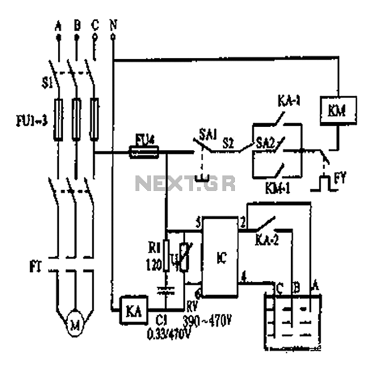
An automatic water tank system is illustrated in the circuit diagram. The circuit employs a PSSR AC solid-state relay, which is a new type of solid-state relay designed for AC applications. Unlike traditional solid-state relays (SSR), this PSSR not...
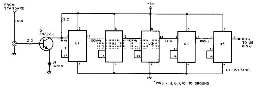
This circuit is designed to be driven by a 1-MHz standard signal with an amplitude of several volts. The components U1 through U5 are 7490 decade counters/dividers, providing a division ratio of 100,000:1. It is possible to tap off...
Using high-beam headlights can significantly enhance visibility while driving, but they can also pose a blinding hazard to other drivers. A simple circuit can be integrated into the headlight system to enable automatic switching between high and low beam...
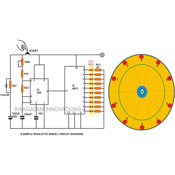
A simple circuit for a 10 LED roulette wheel is presented. Pressing the button initiates the LEDs in a rotational sequence that starts at full speed and gradually decelerates until it halts at a randomly selected LED. The randomness...
This project takes advantage from -HOLD input, which is connected to push-button P1. As long as the -HOLD input is low, truth table's timeouts have no effect because this input serves to disable any state change provoked by timers....
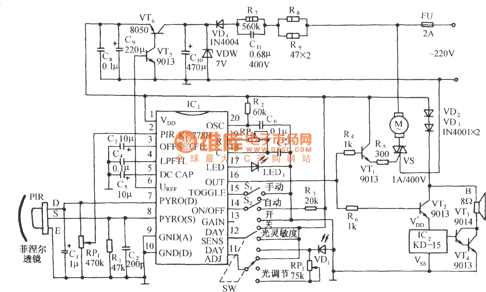
The circuit is depicted in the diagram. It is a control circuit that consists of the infrared-specific integrated circuit KC778B, which serves as the central component. Surrounding it are a pyroelectric infrared sensor head (PIR), a light control and...