
Arduino Panic Alarm Project
The Panic Alarm program is structured as follows: it defines the pin assignments for the relay, switch, LED, and piezo speaker. The setup function configures these pins for input or output as required. In the loop function, the program continuously checks the state of the switch. If the switch is activated (input is HIGH), the relay and LED are turned on, and a tone is played through the piezo speaker. If the switch is not activated, the relay and LED are turned off, and the tone is silenced. The playTone function generates sound by toggling the piezo speaker on and off at a specified frequency and duration.
The circuit design allows for flexibility in alarm signaling, accommodating various external devices that can be controlled via the relay. The integration of the Arduino platform not only simplifies the programming and hardware interaction but also provides a robust framework for expanding functionality, such as integrating additional sensors or communication modules for remote monitoring. This makes the Panic Alarm not only an effective personal security device but also a platform for further exploration and experimentation in electronics.Here is the circuit of an Arduino-based Panic Alarm! The wiring is very simple so that even a novice can construct this interesting circuit without any difficulty. Arduino is a family of microcontrollers (tiny computers) and a software creation environment (Arduino IDE) that makes it easy for you to create programs (called sketches) that can inter
act with the physical world. The Arduino environment has been designed to be easy to use for beginners who have no software or electronics experience. However, try to learn more/refresh your knowledge about arduino platfrom, before constructing this circuit.
If you are new to Arduino, this link will help you get started. In addition, there is an active and supportive Arduino community that is accessible worldwide through the Arduino forums. The forums offer project development examples and solutions to problems that can provide inspiration and assistance as you pursue your own projects.
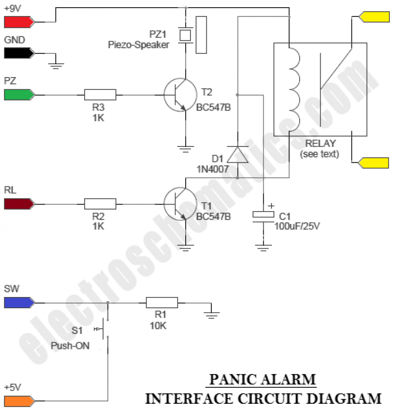
Here is a simple Arduino guide for beginners Panic Alarm circuit consists of two equally important parts. The first part is the ready-made Arduino Microcontroller board, and the second part is an interface circuit which can be wired on a piece of prototyping board.
You can use any standard 9V battery to power the whole circuit, and the Push-ON (push n` hold) switch (S1) to activate the alarm function. An additional Electro-Magnetic Relay (EMR) is also attached to the interface circuit. With the help of this relay, it is easy to energize other (external) high-power blinkers or beepers, if necessary.
// PANIC ALARM - ARDUINO // // by T. K. Hareendran // int rlyPin = 12; // Relay Output Pin int sensPin = 2; // Switch Input Pin int ledPin = 13; // LED output Pin int pzSpeaker = 10; //Piezo-speaker Output Pin int val = 0; // variable for reading the Input Pin status void setup() { pinMode(rlyPin, OUTPUT); // Set Relay as output pinMode(sensPin, INPUT); // Set Switch as input pinMode(pzSpeaker, OUTPUT); // Set Piezo-Speaker as output pinMode(ledPin, OUTPUT); // Set LED as output } void loop(){ val = digitalRead(sensPin); // read input value if (val = HIGH) { // check if the input is HIGH digitalWrite(rlyPin, HIGH); // turn Relay ON digitalWrite(ledPin, HIGH); // turn LED ON playTone(500, 600); delay(100); playTone(500, 800); delay(100); } else { digitalWrite(rlyPin, LOW); // turn Relay OFF digitalWrite(ledPin, LOW); // turn LED OFF playTone(0, 0); delay(300); } } // duration in mSecs, frequency in hertz void playTone(long duration, int freq) { duration *= 1000; int period = (1. 0 / freq) * 1000000; long elapsed_time = 0; while (elapsed_time < duration) { digitalWrite(pzSpeaker, HIGH); delayMicroseconds(period / 2); digitalWrite(pzSpeaker, LOW); delayMicroseconds(period / 2); elapsed_time += (period); } }
🔗 External reference
Related Circuits
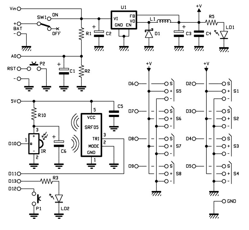
Construct different power conversion circuits using an Arduino microcontroller. The Arduino microcontroller serves as a versatile platform for developing various power conversion circuits. These circuits can include DC-DC converters, AC-DC converters, and other forms of power management systems. The flexibility...
The objective of this post is to consolidate various robot designs and transform them into a new device featuring updated hardware and standardized software, specifically using Arduino, to enhance usability. These robots share three common elements: a mechanical structure,...
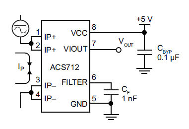
The primary component utilized is the ACS712 sensor from Allegro MicroSystems, designed for measuring current. It offers cost-effective and accurate solutions for AC or DC current sensing in industrial, commercial, and communication systems. A precise, low-offset, linear Hall sensor...
It came to me in a flash. A simple way to see if a fuse has blown without removing it from its holder. Its not often you can design a circuit using just two components, but with just one...
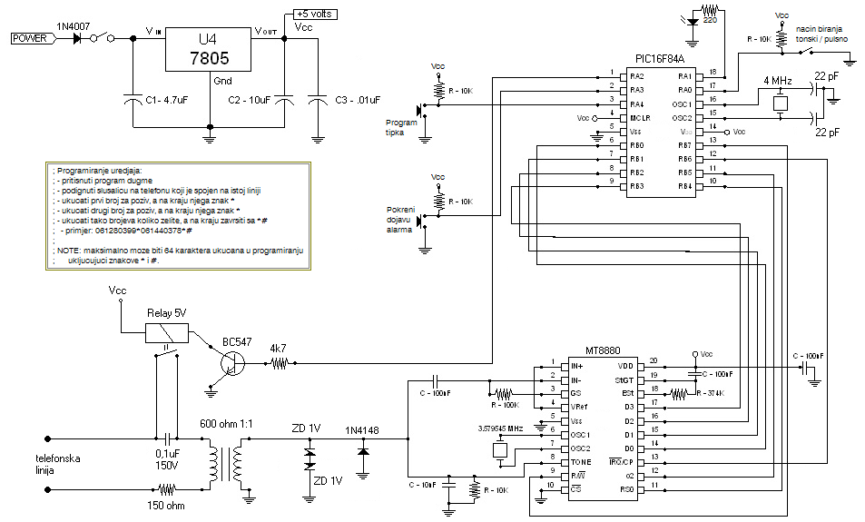
Connect this Alarm Phone Dialer to a device you wish to monitor, such as a high water alarm, low temperature alarm, back window, or garage door. When activated, it will call a series of pre-programmed numbers to notify you...
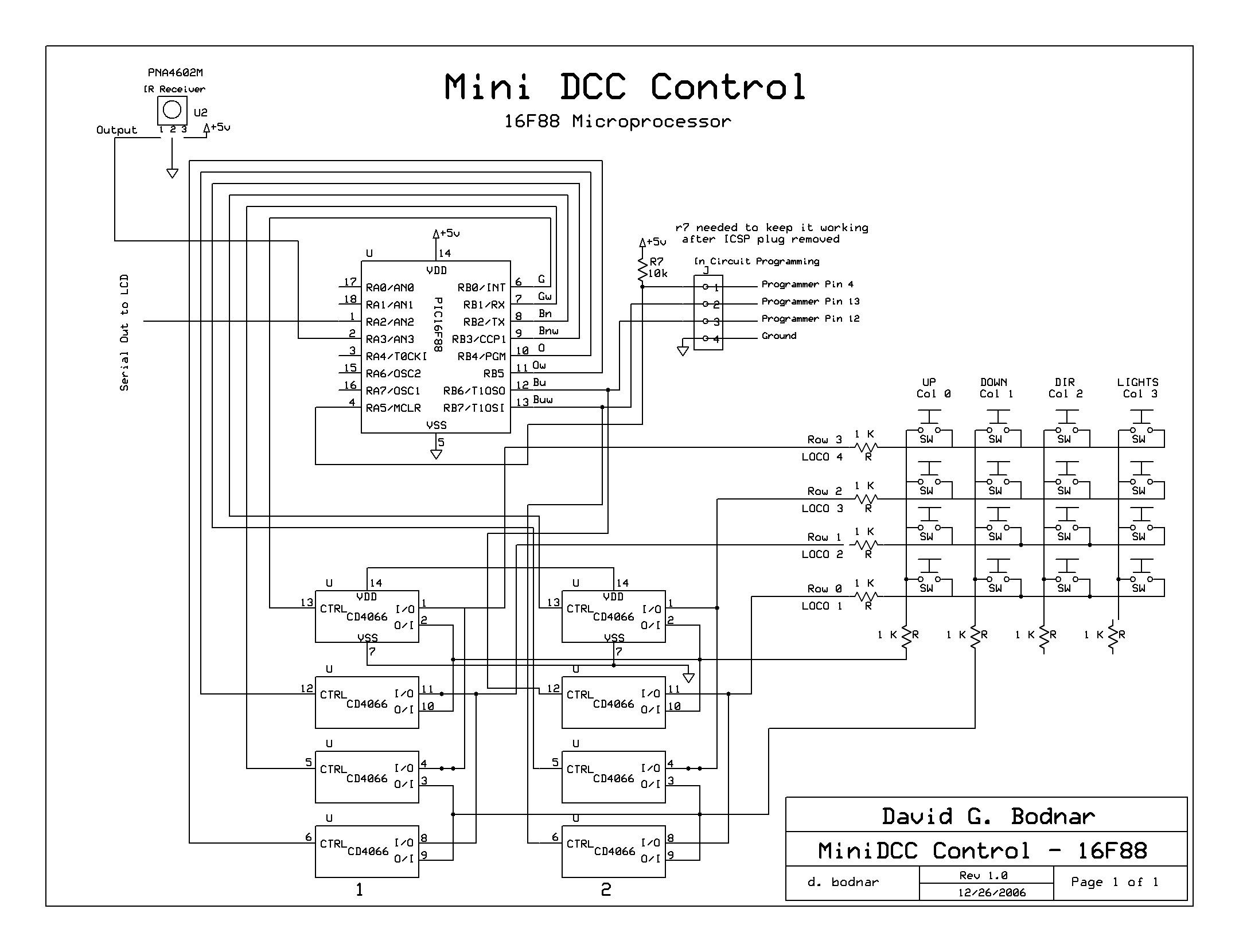
Develop a self-contained unit that can automatically control up to four DCC-equipped engines, starting and stopping them based on their position on a loop of track. The control PIC interacts with the MiniDCC controller through the MiniDCC's keypad. Six...
Warning: include(partials/cookie-banner.php): Failed to open stream: Permission denied in /var/www/html/nextgr/view-circuit.php on line 713
Warning: include(): Failed opening 'partials/cookie-banner.php' for inclusion (include_path='.:/usr/share/php') in /var/www/html/nextgr/view-circuit.php on line 713