
Astable Flip-flops
The astable flip-flop circuit serves as an effective solution for generating periodic signals, notably in applications requiring visual indicators like LED flashers. The configuration leverages two transistors arranged in a feedback loop, where the timing of the flashing is determined by the interplay of the resistors and capacitors in the circuit. The choice of components, particularly the type of transistor and the values of the resistors and capacitors, allows for customization of the flashing frequency and current levels, making the design adaptable for various applications.
In the basic design, the bias resistors ensure that the transistors remain in their active regions, allowing for rapid switching and consistent LED illumination. The use of Darlington transistors enhances the circuit's gain, enabling it to drive higher loads without necessitating substantial component changes. This characteristic is particularly advantageous in applications where power efficiency and load handling are critical.
Furthermore, the introduction of negative feedback not only stabilizes the operation against component variations but also improves the overall performance of the circuit by minimizing the effects of thermal drift and component aging. This robustness is essential for applications in diverse environments where temperature fluctuations can impact circuit behavior.
The design can be further optimized for specific applications by selecting appropriate capacitors and resistors to achieve desired flashing rates, as well as by employing alternative transistor types such as MOSFETs, which offer additional benefits in terms of switching speed and efficiency. The versatility of this astable flip-flop circuit makes it suitable for a wide range of electronic projects, from simple decorative lighting to more complex signaling systems in industrial applications.The familiar astable flip-flop circuit is a handy configuration for making flashers or generating squarewaves. Here is a typical alternating LED flasher with the LEDs in the emitters instead of collectors as is normally done.
(There is another good reason to put them in the emitters - see Karen`s note below. ) The bias resistors are directly conne cted to the supply and are chosen to have a value about 100 times the collector resistor for ordinary gain transistors. The flashing period is approximately the product of this resistance and the capacitance which is about 1 second for the circuit as shown.
The 470 ohm resistors set the LED current and may be reduced for lower battery voltage but remember to also reduce the bias resistors. If no LEDs are desired, the emitters may be directly connected to ground and two out-of-phase voltage squarewaves are available on the collectors.
This is another version of the circuit that uses negative feedback for the bias. This technique is generally more desirable because the feedback ensures that both transistors are in a high-gain, linear mode when power is applied. In actual practice the first circuit will often work "better" with ordinary bipolar transistors since there is no negative feedback slowing the switching.
The feedback makes the circuit more immune to parameter variations due to temperature changes, gain variations, or even component substitution. This version will work with just about any NPN darlington transistor. The bias resistor may be much larger due to the high gain of the darlington so much lower value, non-polar capacitors will give a suitable flash rate.
Of coures, other applications may require different oscillation rates which are easily achieved by changing the capacitor value. Other voltages and currents may be accommodated by changing the collector resistor value. PNP versions of all of these circuits may be built by reversing the polarity of the battery and polarized capacitors.
The high gain of the darlingtons makes it feasible to handle heavy loads either in the emitters as shown or in place of the collector resistors as is commonly done. Lower value bias resistors may be necessary depending upon the load current and the gain of the transistors.
Here is an unusual way to get more power out of the astable flip-flop without resorting to huge capacitors. The emitter current flows through the base-emitter junction much like the LEDs above saturating the output transistors.
The 2N4401 can handle up to 600mA in this circuit but a higher current transistor may be substituted. The base current of the output transistor may be adjusted by changing the 470 ohm resistor, as needed.
Adding another power transistor on each side brings this flasher into the 10 amp range using ordinary bipolar transistors. Only one side needs the extra transistors if only one flashing lamp is required. Just ground the emitter of the low power side. Mosfet power transistors will work in most of these circuits as long as the negative feedback biasing is used.
A capacitor is needed across the mosfet circuit and is generally a good idea in all of the circuits. Some mosfets will exhibit RF oscillations in this circuit (the VN67, for example). Transistors that worked well were: VN10KM, VN88, SK3165, and IRF531. Most power mosfets that require only a couple of volts to turn them on will work up to their current and power ratings. Here is a way to use the circuit at high voltages. The voltage divider resistors in the gate circuit limit the gate voltage to safe levels. The circuit shown flashes two ordinary 7 watt nightlights but the input voltage must be only 90 VRMS.
If the flasher is to be operated directly of off the rectified line voltage, add an 820 ohm, 2 watt resistor in series with each lamp. One lamp may be replaced with a 10k resistor if only one flashing lamp is required. These circuits are useful for purposes other than flashin 🔗 External reference
Related Circuits
The circuit consists of two synchronized multivibrators formed by a pair of 555 timer circuits. It is capable of generating two synchronized pulse signals, with the spacing and frequency adjustable by modifying the time constant. The circuit offers flexibility...
The MC74HC04 IC is a low cost CMOS Hex Inverter. I used this type mainly because, it is what I have, although you can use LS type but, with a little modification or exemptions. More: For 'HC' type: Always...
The objective is to design a square-wave generator with an output range of 0 to +5V. Additionally, the design should allow for the modification of the signal to enable adjustment of the duty cycle of the pulse (PWM). The square-wave...
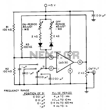
The pulse repetition rate is determined by adjusting switch SI to the desired position, and this rate remains relatively constant even when the resistors that control the on-period and off-period are modified. Resistors R1 and R2 set the biasing...
Function: to trigger a device or operate in free-running mode. Components: Battery, Charger, Battery Connector, Capacitor, Integrated Circuit (IC), Resistor VR1-10K, Resistor R1-1K, Resistor R2. The described circuit functions either to trigger a connected device or to operate in a...
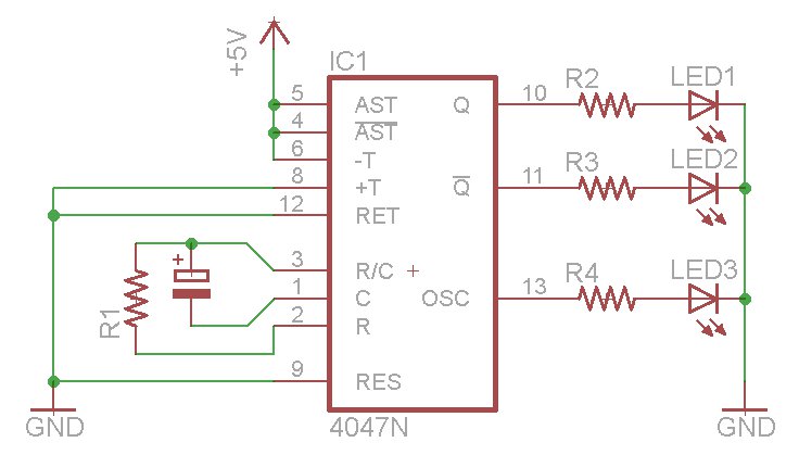
The oscillator output generates a signal that is approximately twice the frequency of Q. The other pins will be considered subsequently. In a brief video demonstration, LEDs are connected to all three outputs, illustrating the alternating behavior of Q...