
Astable Multivibrator I Circuit
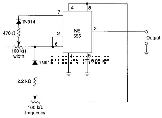
This multivibrator circuit utilizes steering diodes, specifically the 1N914 type, to enable independent control over both the frequency and pulse width of the output waveform. The configuration typically involves two potentiometers, which are employed to adjust the timing components of the circuit.
The first potentiometer is connected in such a way that it influences the charging and discharging time of a capacitor, thereby affecting the frequency of oscillation. The second potentiometer adjusts the discharge path of the capacitor, which in turn modifies the pulse width of the output signal.
The use of steering diodes in this circuit is crucial, as they allow for the selective routing of current, ensuring that the timing characteristics can be altered without affecting the overall stability of the oscillation. The 1N914 diodes are chosen for their fast switching capabilities, making them suitable for high-frequency applications.
Overall, this multivibrator circuit design is versatile and can be used in various applications, such as signal generation, timer circuits, or pulse-width modulation systems. The ability to control frequency and pulse width independently makes it a valuable tool in electronic design and experimentation. In This multivibrator circuit frequency and pulse width can be separately controlled by using steering diodes (1N914) and two potentiometers. 🔗 External reference
Related Circuits
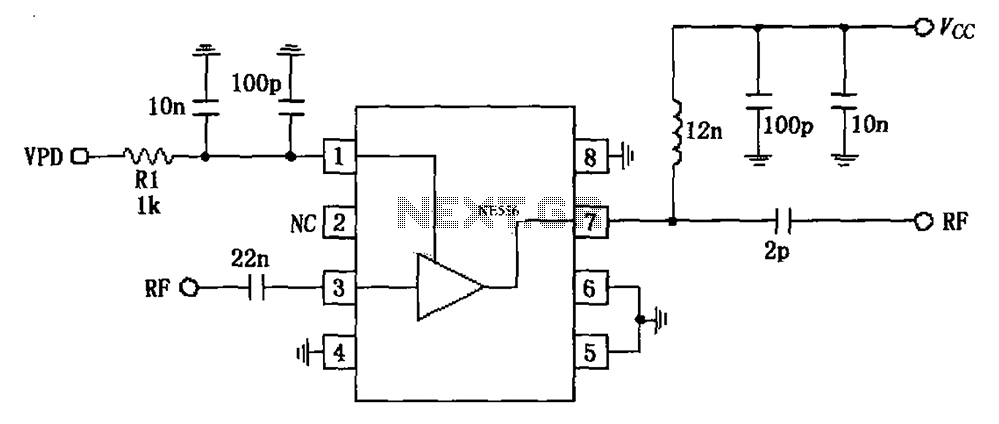
The circuit is based on an 880 MHz RF2347 low noise amplifier application. The radio frequency (RF) signal enters through input pin 3, and after amplification, the output is available at pin 7. The amplifier is directly coupled to...
The 555 timer is utilized as a clock source to drive the RS7490 decimal counter, providing a BCD output to a 7-segment LED display. The clock frequency can be adjusted by changing the value of resistor R1. The circuit operates...
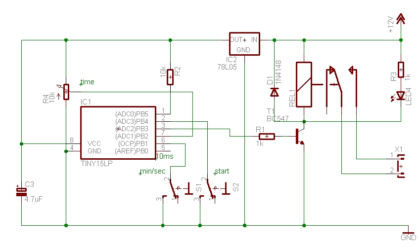
The time can be set using a potentiometer ranging from 1 minute to 1023 minutes, approximately 17 hours. A pushbutton initiates the timing process, activates a relay, and the timer will deactivate the relay once the set time has...
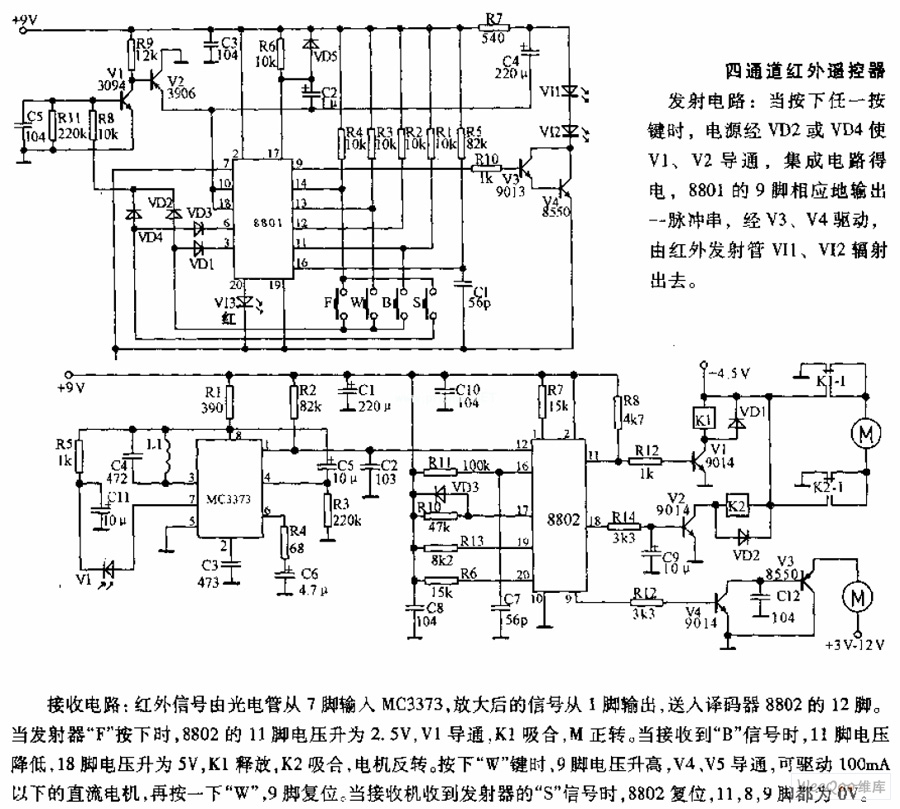
The receiving circuit involves an infrared signal being input to the MC3373 from pin 7 via a phototube. The amplified signal is output from pin 1 and sent to pin 12 of the decoder 8802. When the transmitter F...
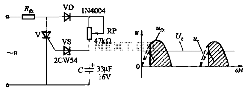
Circuit characteristics: A simple phase shift range of 180 degrees; exhibits good linearity and control accuracy compared to the first two options, making it suitable for low voltage applications, particularly in less demanding electroplating and electrolysis power supplies. The described...
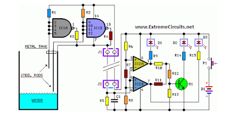
Simple two-wire remote monitoring unit with a three-LED level display, powered by a 9V battery. The entire project was developed at the request of a friend. The remote monitoring unit is designed to provide a straightforward solution for level indication...
Warning: include(partials/cookie-banner.php): Failed to open stream: Permission denied in /var/www/html/nextgr/view-circuit.php on line 713
Warning: include(): Failed opening 'partials/cookie-banner.php' for inclusion (include_path='.:/usr/share/php') in /var/www/html/nextgr/view-circuit.php on line 713