
Four channels infrared remote controller circuit diagram
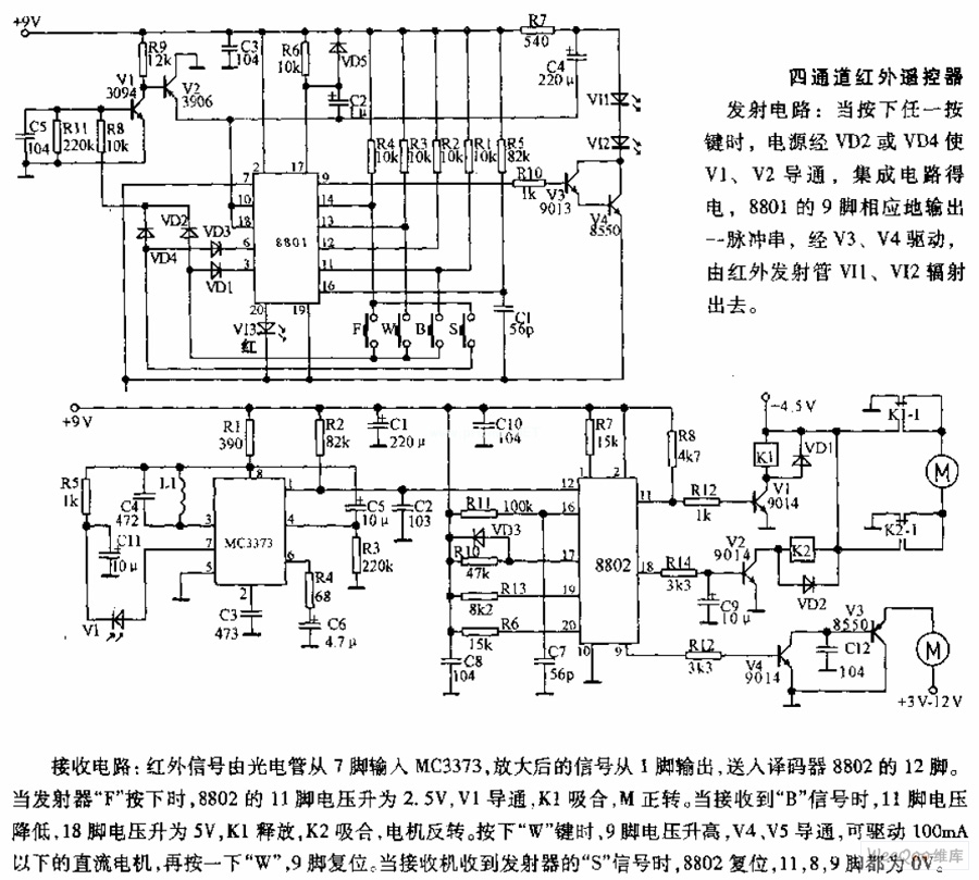
The described receiving circuit is designed to process infrared signals through a series of components that work cohesively to control motor operations based on specific signal inputs. The circuit begins with an infrared signal captured by a phototube, which serves as the input mechanism for the MC3373. The MC3373 amplifies this signal, and the output is directed to the decoder 8802.
The decoder 8802 plays a crucial role in interpreting the signals received. The activation of the transmitter F results in a voltage increase at pin 11, which is critical for initiating motor operations. The transistor V1 is activated by this voltage, which in turn energizes relay K1, allowing the motor M to rotate forward. This forward motion indicates that the system is responsive to the transmitter's commands.
When the circuit receives the B signal, a drop in voltage at pin 11 occurs, while pin 18 sees an increase to 5V. This change in voltage levels triggers the release of K1 and engages K2, resulting in the motor reversing its direction. This feature provides the circuit with the ability to respond dynamically to different signals, enhancing its functional versatility.
The circuit also includes a function controlled by pressing W, which raises the voltage at pin 9. This action activates transistors V4 and V5, enabling the operation of low-power DC motors (under 100mA). The ability to drive these motors allows for additional functionalities, such as movement or other mechanical actions that can be controlled remotely.
The reset function is also integral to the system's operation. By pressing W a second time, pin 9 is reset, ensuring that the circuit can return to a neutral state. Furthermore, the detection of the S signal from the transmitter prompts the 8802 to reset completely, bringing both pins 8 and 9 to 0V. This comprehensive design allows for effective control of motor functions based on infrared signal inputs, showcasing the circuit's capability for remote operation and automation.The receiving circuit: the infrared signal is inputed to MC3373 from 7 foot by phototube, the amplified signal outputs from 1 foot, it is transported into the 12 foot of decoder 8802. When the transmitter F is pressed, the voltage of 8802`s 11 foot up to 2. 5V, V1 turns on, K1 pulls in, M is forward rotation. When it receives B signal, 11 foot`s vo ltage drops, 18 foot`s voltage up to 5V, K1 releases, K2 pulls in, the motor is reversal rotation. Pressing W, 9 foot`s voltage rises, V4, V5 turn on, it can drive the DC motors which under 100mA, pressing W again, 9 foot resets. When the receiver receives the transmitter`s S signal, 8802 resets, 8, 9 feet are all 0V. 🔗 External reference
Related Circuits
This schematic illustrates a simple yet effective LED dimmer circuit utilizing the well-known voltage regulator IC LM317T. The LM317T can function as a current regulator, as demonstrated in this circuit. It features ten super bright white LEDs, although the...
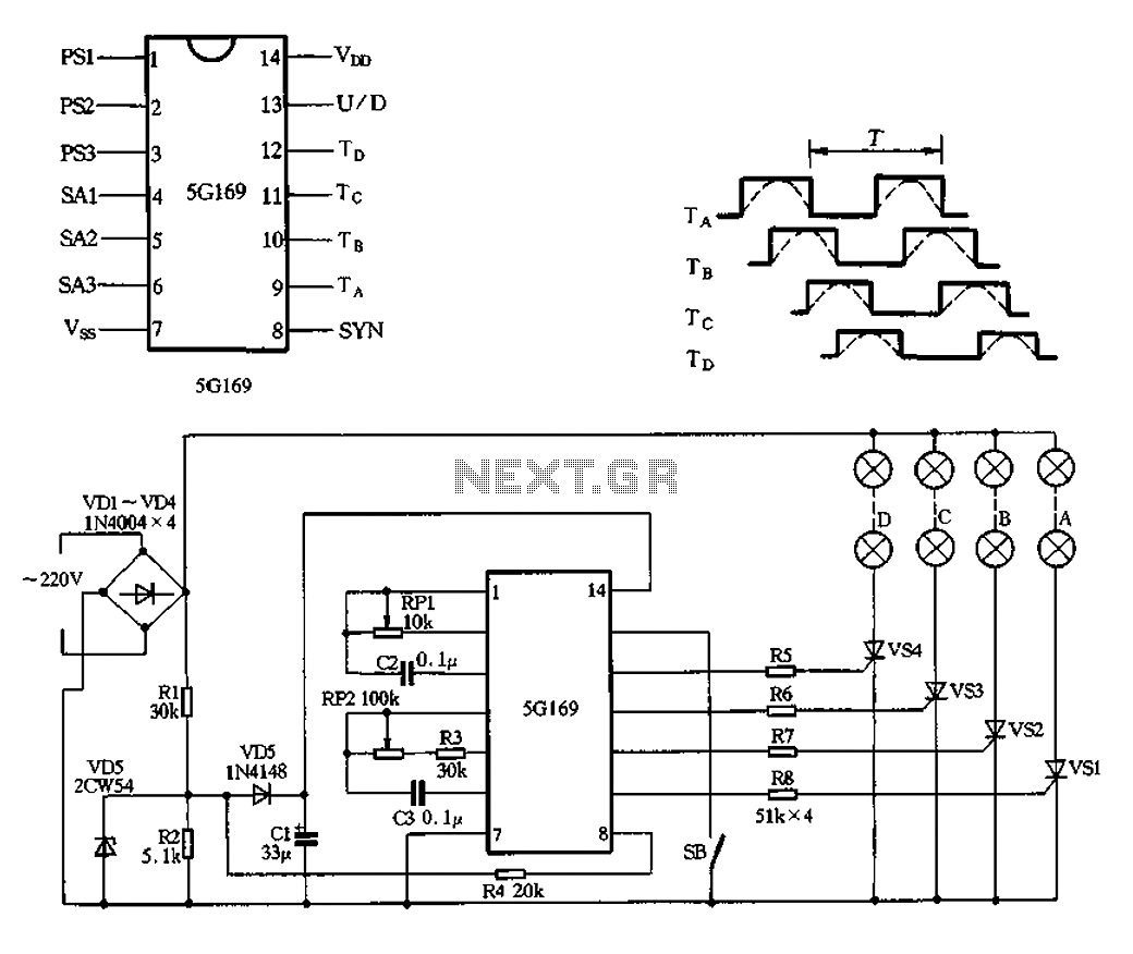
The circuit features an AC input from VDI, which is converted to pulsating DC power using a VD4 full-wave bridge rectifier to power four lights. Resistors R1 and R2, along with diode VD5, form a simple circuit, while VD6...

For individuals seeking LED-based footswitching without the inconvenience of battery installation, a battery-less LED-based footswitch modification is being developed for 2-channel amplifiers. This solution is designed to work with the existing TRS jack and footswitch, and it will involve...
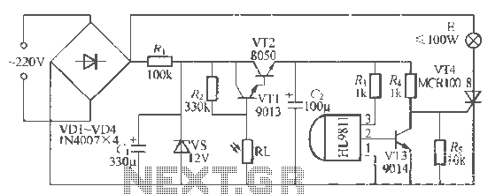
The H1.9811 single-channel flash control integrated circuit from Wuxi Love Core Microelectronics Co., Ltd. is designed for controlling flashing warning lights in road barricades. It features an integrated internal RC oscillator, frequency divider, output buffer amplifier, shaping circuit, and...

The power amplifier circuit utilizing MOSFET technology has gained significant popularity due to its aggressive sound characteristics when compared to traditional transistors and integrated circuits. It offers both low-frequency and high-frequency responses and is known for its durability. Generally,...
The device being constructed will serve as a metal detector, capable of locating metal objects such as coins, nails, and keys, including car keys that may be misplaced. It can also detect gold, although it may not possess industrial...