
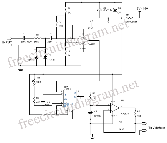
Astable Multivibrator Using 741 Op-Amp
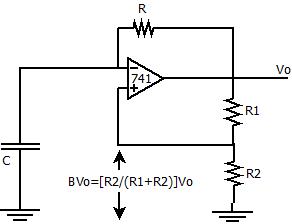
The described positive feedback comparator circuit serves as a fundamental building block in various electronic applications, particularly in generating square wave signals. The astable multivibrator configuration is characterized by two unstable states, allowing for continuous oscillation without the need for external triggering. The operational amplifier (op-amp) used in this circuit, such as the IC 741, is essential for achieving the desired gain and response time.
In this configuration, the timing of the oscillation is determined by the values of the resistor `R` and the capacitor `C`, which together define the time constant of the RC integrator. The charging and discharging cycles of the capacitor dictate the frequency of the output waveform. When the capacitor voltage `Vc` exceeds the threshold set by the non-inverting terminal voltage, the op-amp output switches states, providing a square wave output.
The hysteresis introduced by positive feedback is crucial in preventing false triggering due to noise or minor fluctuations in input voltage, thereby stabilizing the output. The feedback factor, represented by the ratio of resistors R1 and R2, can be adjusted to modify the sensitivity of the circuit, allowing for flexibility in various applications.
Overall, the astable multivibrator circuit using a positive feedback comparator is widely utilized in timer applications, pulse-width modulation, and signal generation, demonstrating the versatility and effectiveness of operational amplifiers in electronic design.The positive feedback comparator circuit increases the gain ofthe op-amp, which helps to switch very fast between the two states of a multivibrator. The positive feedback also provides hysteresis to the circuit. A capacitor `C` is connected to the inverting terminal of the Op-Amp with its other end grounded. The capacitor along with the resistor `R` acts as a RC integrator. The vol;tage across the capacitor is given by Vc. Thebelow figure demonstrates the working of an Astable Multivibrator using IC 741 Operationalamplifier, consisting of a comparator circuit having a positive feedback with a feedback factor. Now, the op-amp has a voltage of `Vc` at the inverting terminal and [R2/(R1+R2)]Vo atthe non-inverting terminal, giving rise to a voltage equal to+Vsat or -Vsat at the output.
On the other hand at the inverting terminal, the capacitor tries to charge to +Vsat, which is available to the capaciror through `R`. but on the way to +Vsat, when the capacitor reaches at a potential equal to the potential at the non-inverting terminal of the op-amp.
Since the op-amp behaves as a comparator circuit, the output changes from +Vsat to -Vsat, because the inverting potential is greater than non-inverting potential. 🔗 External reference
Related Circuits
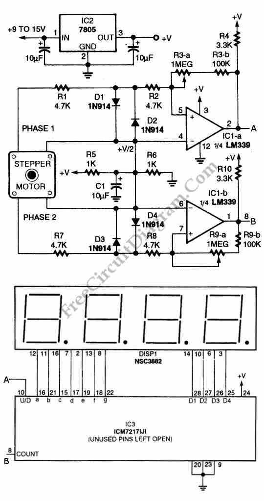
The circuit illustrated in the schematic diagram below allows for the visualization of the direction and shaft rotation of a stepper motor on an LED display. Instead of employing a digital rotation encoder as an input, this circuit utilizes...
Testing whether a transistor is shorted or open is typically performed using an ohmmeter. The test involves checking if current can flow between the base and emitter or the collector. To effectively test a bipolar junction transistor (BJT) for shorted...
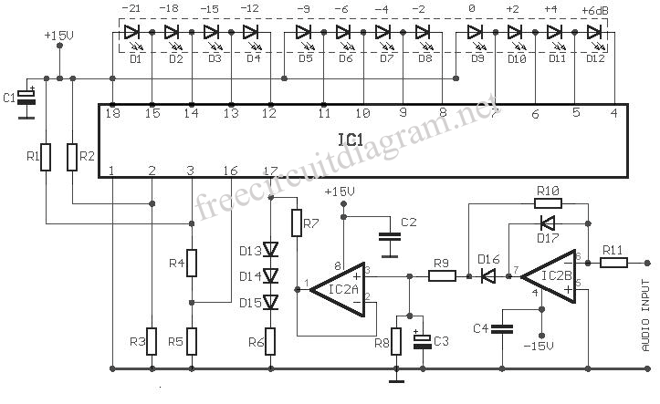
This circuit utilizes the SIEMENS and UAA180 rectification measurement circuits for accurate signal processing, centered around the TL072 integrated circuit (IC2B). Calibration occurs in 3dB increments, ensuring a high level of precision for measuring incoming acoustic signals. The LEDs...
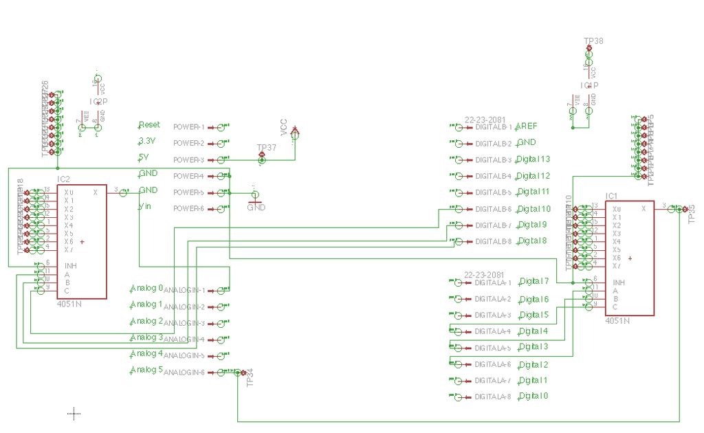
Inspired by a previous project, a unique design was developed that incorporates an umbrella capable of playing musical notes when pressed. For additional information regarding the 4051 chip, which functions as a multiplexer or demultiplexer, refer to resources available...
A frequency meter is commonly used in speed sensors, tachometers, and for measuring recurring signals. This frequency-to-voltage converter (FVC) can be utilized to convert frequency into a digital or analog tachometer output. The circuit comprises three main blocks. The...
Spectrum-analyzer project 2007 update. Since the development of the wide-band VCO almost 10 years ago, the entire spectrum-analyzer project has progressed significantly. The spectrum analyzer project initiated in 2007 focuses on the development and enhancement of a wide-band Voltage Controlled...
Warning: include(partials/cookie-banner.php): Failed to open stream: Permission denied in /var/www/html/nextgr/view-circuit.php on line 713
Warning: include(): Failed opening 'partials/cookie-banner.php' for inclusion (include_path='.:/usr/share/php') in /var/www/html/nextgr/view-circuit.php on line 713