
Digital Encoder Circuit Using Stepper Motor
The circuit operates by utilizing a stepper motor, which is a type of motor that divides a full rotation into a number of equal steps. This allows for precise control of the motor's position and speed. The LED display serves as a visual output, indicating the current direction of rotation and the specific position of the motor shaft.
The schematic typically includes a microcontroller that processes input signals and determines the appropriate step sequence for the stepper motor. The microcontroller interfaces with the motor driver, which amplifies the control signals to drive the motor coils. The stepper motor is connected to the driver in a configuration that allows for full-step or half-step operation, depending on the desired resolution.
The LED display is connected to the microcontroller, which sends signals to illuminate specific segments of the display based on the motor's position and direction of rotation. This feedback mechanism is crucial for applications where precise motor control and real-time monitoring are necessary.
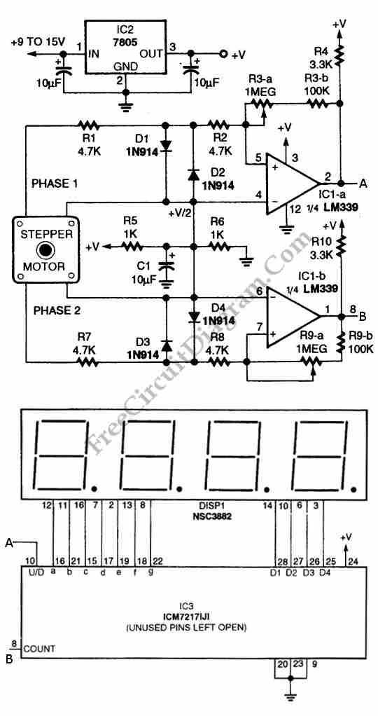
In summary, this circuit effectively combines a stepper motor with an LED display to provide a comprehensive solution for visualizing motor position and direction, replacing the need for more complex digital encoders while maintaining accuracy and reliability in motor control applications.Using circuit depicted in the schematic diagram below, the direction and shaft rotation of stepper motor can be seen on the LED display. Alternative to digital rotation encoder as a digital encoder input, this circuit uses a stepper motor.
Here is the schematic diagram of the circuit: 🔗 External reference
Related Circuits
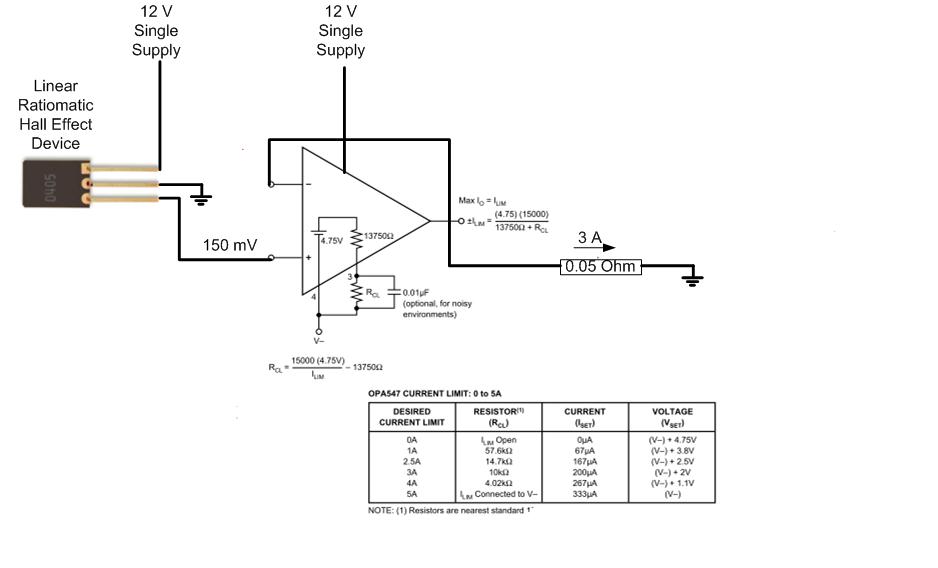
The proposed approach would dissipate (12V)(3A) = 36 watts, which results in significant heat generation in the circuit. This necessitates consideration of two alternatives: 1) Operating the op-amp at a lower supply voltage, if feasible, or 2) Utilizing a...
This three-band equalizer circuit is an active filter network designed for bass, midrange, and high audio frequencies. It utilizes the LM833 operational amplifier from National Semiconductors. The output of this three-way graphic equalizer is intended to be DC coupled;...
The circuit consists of inverter and charger sections. The inverter section utilizes the NE555 timer, while the charger section is based on the LM317 adjustable regulator. In the inverter section, the NE555 is configured as an astable multivibrator, generating...
This project involves an automatic street light or lamp circuit designed to activate outdoor lights, such as garden lamps and night lights, automatically at sunset and turn them off at sunrise. The circuit is sensitive and versatile, capable of...
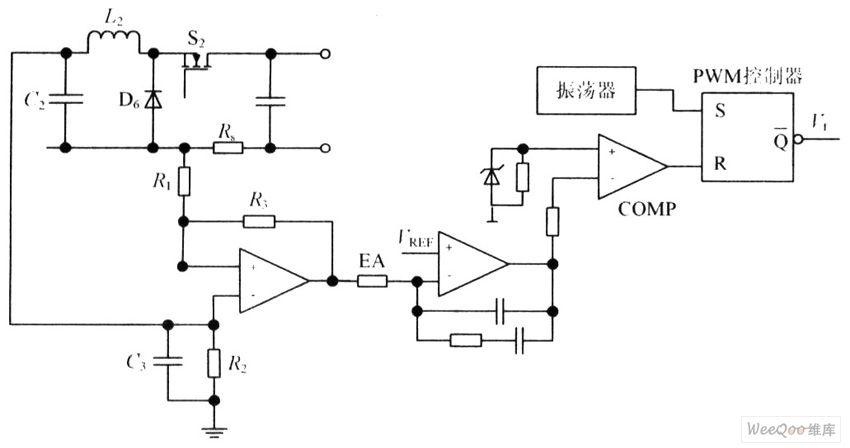
The circuit is capable of enhancing the system power factor to a value exceeding 0.99. It effectively reduces the waveform distortion of the input supply current, ensuring compliance with GB15144 standards, with a distortion index lower than level L....
This is a 100 Watt inverter circuit designed with a minimal number of components. The circuit utilizes the CD4047 integrated circuit from Texas Instruments to generate 100 Hz pulses, and it employs four 2N3055 transistors to drive the load....