
Voltmeter To Frequency Meter Using 4528
The frequency-to-voltage converter (FVC) circuit is a critical component in various applications, particularly in speed measurement and monitoring systems. The design typically consists of three primary functional blocks: the squarer, the voltage converter, and the output stage.
The squarer block is responsible for transforming the incoming frequency signal into a square wave. This transformation is essential because many subsequent processing stages in the circuit require a clean, square wave input for accurate operation. The squarer is designed to handle high input voltages, specifically up to 400V, which makes it suitable for industrial applications where such voltages are common. The capacitor C1 must be appropriately rated to ensure safe operation at these voltage levels, preventing damage to the circuit.
Following the squarer, the next block is the frequency-to-voltage conversion stage. This stage takes the square wave output and converts it into a proportional voltage. The output voltage corresponds to the frequency of the input signal, allowing for easy measurement and interpretation. This block may utilize operational amplifiers and other analog components to achieve precise voltage conversion, ensuring that the output is linear and accurately reflects the input frequency.
The final block is the output stage, which can be configured to provide either a digital or analog output. For digital applications, the output may be fed into a microcontroller or digital display, while for analog applications, it may drive a standard analog meter or other devices that require a voltage input. The design of the output stage will depend on the specific requirements of the application, including the desired output range and the load characteristics.
Overall, the frequency-to-voltage converter circuit is a versatile tool in electronic measurement systems, providing a reliable means of converting frequency signals into usable voltage levels for further processing or display. Proper component selection, particularly for high-voltage applications, is essential to ensure the longevity and accuracy of the circuit.Normally we often encountered the frequency meter can be used in speed sensor, tachometer, measurement or signal recurring. This frequency to voltage converter (FVC) can be used to change the voltage into a digital or analog tachometer.
Circuit that consists of three blocks. The first block is squarer, the input signal to a square wave. This block is protected from high input voltage up to 400V, but remember this only works if the value of capacitor C1 is for 400V 🔗 External reference
Related Circuits
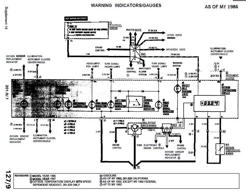
The 1989 2.6 outside thermometer (Celsius) has malfunctioned and stopped displaying readings. A replacement unit was sourced from an eBay seller. The malfunctioning outdoor thermometer likely employs a thermistor or a similar temperature-sensing component to measure ambient temperature. In a...
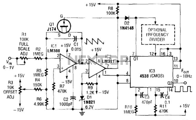
In this circuit, capacitor CI is charged to a fixed reference level and then discharged. The integrator IC1 charges CI until IC1 has a -6.2 V output, at which point comparator IC2 outputs a low signal. FET Q1 triggers...
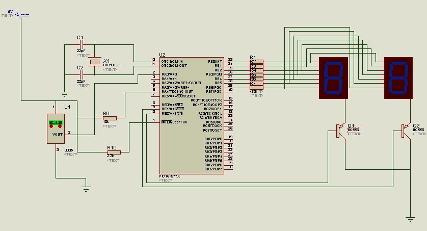
The circuit utilizes the LM35 temperature sensor to measure temperature in the range of 0 to 99 degrees Celsius and displays the readings using two seven-segment displays. It is designed to activate devices through the RC pins; for instance,...
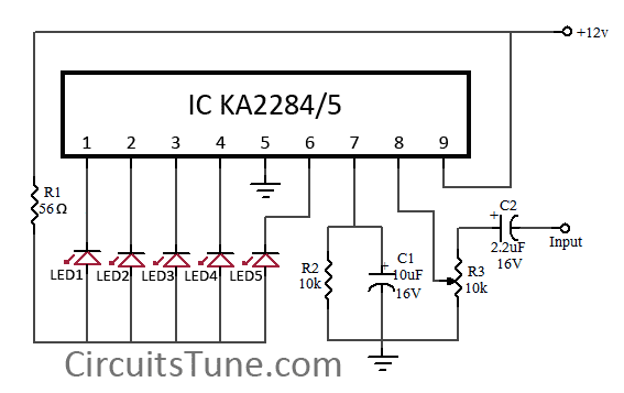
This is a simple circuit diagram of a 5-LED audio VU meter utilizing the ICs KA2284 or KA2285. The KA2284 and KA2285 are monolithic integrated circuits designed as logarithmic display driver ICs. They serve as bar-type display drivers for...
This article continues the AT90S4433 Microcontroller series. It is recommended to read the previous articles on Atmel Microcontroller programming. This time, a frequency counter is designed to measure frequencies from 1Hz to 100MHz. Alternatively, it can be used to...
The circuit is drawn for measurement of acceleration from 1000 mg until + 1000 mg. It can be placed in the car and be supplied from the sheath of the electric lighter. The circuit includes one indicative LED and...
Warning: include(partials/cookie-banner.php): Failed to open stream: Permission denied in /var/www/html/nextgr/view-circuit.php on line 713
Warning: include(): Failed opening 'partials/cookie-banner.php' for inclusion (include_path='.:/usr/share/php') in /var/www/html/nextgr/view-circuit.php on line 713