
AT89C2051/4051 Stepper Motor Interface

The M1 stepper motor is a crucial component in various applications, particularly in robotics and automation, where precise control of movement is essential. The motor's design, comprising five pins, allows for straightforward connectivity and control. The common pin serves as the reference point for the coils, which are energized in a specific sequence to achieve rotation. The measured resistance of approximately 75 Ohms indicates that the coils are designed to operate efficiently at low voltages, making them suitable for microcontroller applications.
The driving current requirement of 60mA per coil at a +5V supply ensures that the stepper motor operates within its specified limits, preventing overheating and potential damage. The use of the ULN2003 Darlington transistor array is a strategic choice, as it facilitates higher current handling capabilities while interfacing with the lower current outputs of the 2051 chip. This configuration allows for reliable control of the stepper motor without overloading the microcontroller.
The connection of output pins P1.4 to P1.7 to the ULN2003 enables the microcontroller to control the stepper motor's rotation direction and speed through pulse-width modulation (PWM). The inclusion of four 4.7k resistors serves to limit the current flowing from the 2051 chip to the ULN2003, ensuring that the microcontroller operates safely within its current specifications while still providing sufficient drive to the motor.
The optional serial port interface expands the versatility of the stepper motor application, allowing for integration into systems requiring remote control or communication with other devices. This feature is particularly beneficial in complex projects where feedback and control from a host computer or microcontroller are necessary.
In summary, the M1 stepper motor circuit exemplifies a well-designed system for controlling stepper motors using a microcontroller, with careful consideration given to current requirements, component selection, and circuit configuration. The availability of educational resources further enhances understanding and application of stepper motors in various fields.M1 is a stepper taken from an old disk drive. There are five pins, i. e. , common, coil 1, 2, 3 and 4. Resistance measured between common pin and each coil is about 75 Ohms. Driving current for each coil is then needed about 60mA at +5V supply. A Darlington transistor array, ULN2003 is used to increase driving capacity of the 2051 chip. Each outputprovides 500mA max at 50V. P1. 4 to P1. 7, four output pins are connected to the input of the ULN2003 as shown in the circuit. Four 4. 7k resistors help the 2051 to provide more sourcing current from the +5V supply. The serial port is optional for your exercises. Many have provided useful technical, and application of using stepper, see the links below. Jones on Stepping Motors Jones provides a tutorial covering the basic of stepping motors and control systems, including physics of the motor, circuits and software for motor control. 🔗 External reference
Related Circuits
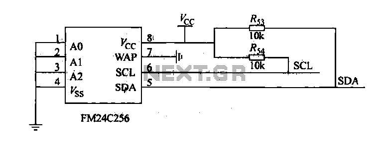
The FM24C256 is utilized as a slave interface circuit in an I2C bus configuration, with the address format specified in Table 27-3. The address pins A2, A1, and A0 are set to low; however, for extended storage capacity, adjustments...
The resistors R18 and R22, which were intended to be connected to pin 8 of U4, were incorrectly connected to pin 9. The current versions have been corrected. There is a minor error in the component layout where two...
Car and Motorcycle Battery Tester Circuit. Going camping today often requires bringing various electronic devices for daily activities or entertainment. Typically, a charged lead-acid battery and a power source are essential. The Car and Motorcycle Battery Tester Circuit is designed...
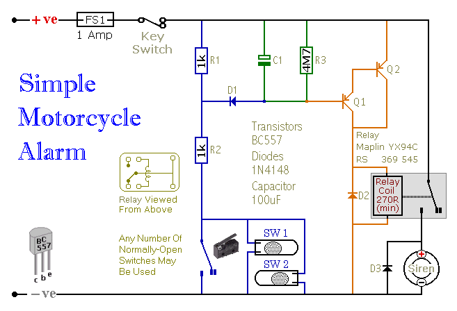
Motorcycle Alarm Number 4. This is a simple, easy-to-build, transistor-based motorcycle alarm. It is designed to operate at 12 volts; however, it can be adapted by changing the relay to a different specification. This motorcycle alarm circuit utilizes a transistor...
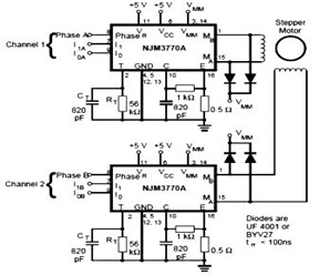
The schematic below represents a typical stepper motor driver application utilizing the NJM3770A. As illustrated in the diagram, the single-channel stepper motor drivers NJM3717 and NJM3770A operate independently and are not synchronized. The circuit design features the NJM3770A, a dedicated...
The Star Delta starting method is a motor starting mechanism that minimizes the large amount of starting current drawn by motors. As the name suggests, the Star Delta method involves supplying the motor with 1/sqrt(3) (approximately 58%) of the...