
Motorcycle Alarm Number 4

This motorcycle alarm circuit utilizes a transistor as the main switching element, providing a reliable method for activating an alert system when unauthorized access is detected. The design typically includes a relay that controls the alarm sound or light indicator, which can be triggered by various sensors or switches, such as a tilt sensor or a door switch.
The circuit operates on a standard 12-volt power supply, commonly found in motorcycles, ensuring compatibility with the vehicle's electrical system. The transistor is configured in a way that allows it to amplify the current from the sensor to energize the relay. When the sensor is activated, the transistor switches on, allowing current to flow through the relay coil, which then closes the relay contacts and activates the alarm.
For enhanced functionality, the alarm can be modified by selecting a relay with different specifications, which may allow for higher voltage operation or additional features such as a longer alarm duration or alternative signaling methods. The circuit can also be protected against false alarms through the use of diodes and capacitors that filter out noise and provide stability to the operation.
Overall, this motorcycle alarm design prioritizes simplicity and effectiveness, making it suitable for hobbyists and individuals looking to add a layer of security to their motorcycle.Motorcycle Alarm Number 4. This is a simple - easy to build - transistor based motorcycle alarm. It`s designed to work at 12-volts. But - if you change the relay for one. 🔗 External reference
Related Circuits
The primary components of this doorbell circuit include two NE555 timer integrated circuits (ICs). When the switch S1 is pressed momentarily, the loudspeaker emits a bell tone for the duration determined by the time period of the monostable multivibrator...
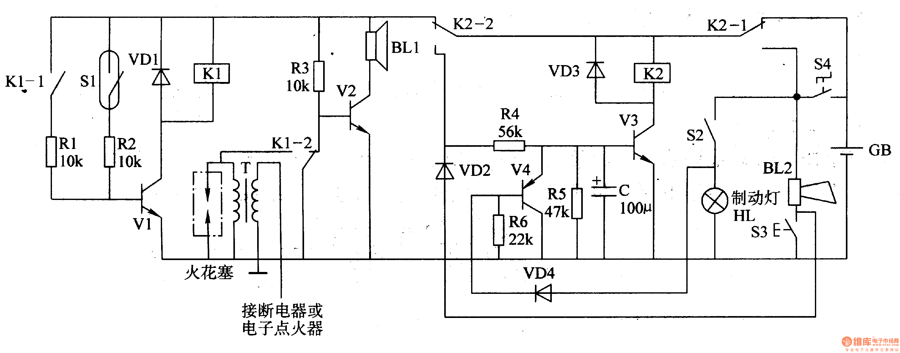
The circuit comprises a trigger circuit, an alarm control circuit, and a reset circuit for the alarm. The trigger circuit includes mercury switches (S1), a resistor, transistors (V1), and a relay (K1). The alarm control circuit is made up...

This is a simple smoke alarm circuit using a timer IC, the NE555. The circuit operates by illuminating a Light Dependent Resistor (LDR) with a lamp. When smoke obscures the light from the lamp, the resistance of the LDR...
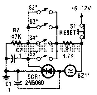
Four parallel switches are employed to monitor four positions. When any switch is closed, SCR1 is triggered, activating the alarm. The alarm is designed to be of the non-interrupting type. The circuit consists of four parallel switches, each representing a...
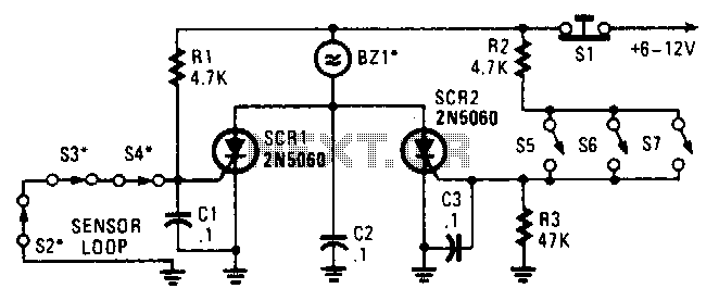
Two SCRs are utilized with two sensor loops. One loop employs series switches, while the other loop employs parallel switches. When a switch is actuated, the SCR is triggered. The alarm is designed to be a non-interrupting type. The circuit...

This is a new design for a universal gear indicator that can be fitted to any motorcycle as an aftermarket accessory. Its main advantage is that its operation depends entirely on the gear shift lever movement, instead of connecting...