
ATmega8 and Hall Sensor A1302
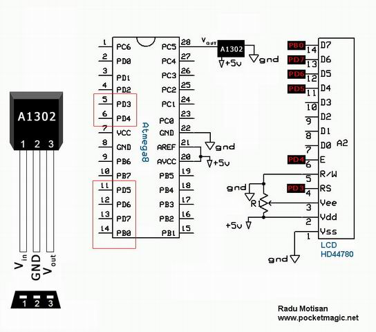
The A1301 and A1302 Hall-effect sensors are highly versatile devices capable of accurately detecting magnetic fields and translating them into a corresponding voltage output. The continuous-time operation allows for real-time monitoring of magnetic field changes, making these sensors suitable for various applications, including proximity sensing, motor control, and current sensing.
The typical connection setup involves powering the sensor with a stable 5V supply. The output voltage from the sensor is ratiometric, meaning it varies linearly with the magnetic field strength. The output voltage can be directly interfaced with a microcontroller’s ADC, which is crucial for digital signal processing. The 8-bit ADC can convert the analog voltage levels into digital values, facilitating easy interpretation of the magnetic field strength.
In practical applications, the sensor can be used to control other electronic components. For instance, the output voltage can be used to switch an NPN transistor, which in turn can control larger loads such as LEDs or motors. The choice of a 460-ohm resistor between the output pin and the base of the transistor is critical to ensure proper biasing, allowing the transistor to operate within its active region.
Furthermore, the behavior of the sensor in response to different magnetic poles provides insights into its functionality. The ability to differentiate between the north and south poles of a magnet enhances its application potential in systems requiring directionality, such as compasses or position sensors.
Regarding the sensor's maximum magnetic field capability, it is essential to consult the manufacturer's specifications to determine the safe operating limits. Exceeding these limits may lead to non-linear responses or permanent damage to the sensor. Therefore, for applications involving strong magnetic fields, such as 1 tesla, careful consideration and potentially additional circuitry may be required to protect the sensor and ensure accurate readings. Overall, the A1301 and A1302 Hall-effect sensors are robust components that offer reliable performance in various electronic and automation applications.The A1301 and A1302 are continuous-time, ratiometric, linear Hall-effect sensor ICs. They are optimized to accurately provide a voltage output that is proportional to an applied magnetic field. These devices have a quiescent output voltage that is 50% of the supply voltage. If you connect this voltage output to a microcontroller`s ADC port, having the maximum reference voltage of 5V = value 255 for 8bit ADC, the 2. 5V will return a value of 128. I`m not sure the conductor would generate enough magnetic field to trigger the sensor, in my tests above I`ve used a strong neodymium magnet and I was getting readings from 2-3cm the most. - simply connect the sensor to a 5V supply, and use the Vout PIN to open the Base of a NPN transistor through a 460Ohm resistor.
Connect the transistor`s emitter to (-), and between the colector and (+5V) put your led. - the sensor will output a voltage of 0. 2. 5V on Vout proportional to the nearby magnetic field. So if it senses the magnetic field of the conductor, it will trigger the transistor. Thank you very much for reply, I have tested as you told, when I brings the magnet pole near to A1302 led feds away. ( in multimeter Voltage reduced to 0. 71 volt from 2. 42 volt ) and led become brighter when I brings the magnet near to opposite side of the A1302(also voltage level increased showing in multimeter.
) Touching the metal prob connected with base of the first stage transistor makes the LED OFF momentarily and then it glows up again, and there is no effect found when I borught the prob to a AC current flowing conductor. Vrei sa folosesti un senzor HAL pentru a controla viteza Interesanta idee, sper sa poti sa pui niste poze daca iti iese.
Am sa-ti raspund in engleza, poate intereseaza si pe altii. If you look carefully at the details above, you will see the sensor returns 128 in idle mode (no significant magnetic field), 128. 255 if the field produced by the north pole of a magnet, or 0. 128 for the south pole. For these values, being read using one ADC port, at a resolution of 8bits, it means you have aprox. 2. 5V in idle mode, 2. 5-5V for north pole field, and 0. 2. 5V for south pole field. But, I still have a doubt: about this A1302 (or A1301), there is a maximum magnetic field supported I mean, if I put 1 tesla near the sensor, for example, the response will still be aprox.
proportional 🔗 External reference
Related Circuits
The photodiode is utilized to detect infrared (IR) light reflected from an object. However, it also picks up IR light generated by ambient conditions, which can lead to false detections. To mitigate this issue, it is essential to filter...
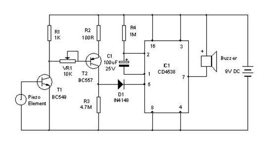
A vibration sensor or piezoelectric vibration sensor circuit diagram. It emits a loud beep when an attempt is made to break a door or window. The alarm automatically ceases after three minutes. The circuit utilizes a piezo element as...
There are many measurement systems that would be more suitable if a logarithmic scale is used, especially when attempting to mimic human sensory responses. Most... Logarithmic scales are particularly effective in representing a wide range of values in a compact...
The schematic diagram has been modified to include a 220µF smoothing capacitor connected between the base of transistor Q1 and ground. This addition effectively mitigated the issue of relay chatter, which involved rapid on/off switching at light levels. The...
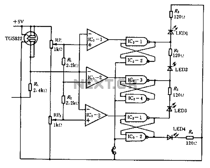
Ceramic gas sensors can be utilized to analyze the content of alcohol vapor. With the appropriate sensor circuit, it is possible to detect blood alcohol content. The operating principle is straightforward: if blood alcohol content is present in a...
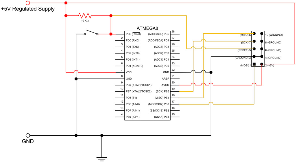
This tutorial continues from the ATmega8 Breadboard Circuit Part 1, where a small power supply was built on a breadboard. In this part, the ATmega8 microcontroller will be added along with an interface for programming. The first step is...
Warning: include(partials/cookie-banner.php): Failed to open stream: Permission denied in /var/www/html/nextgr/view-circuit.php on line 713
Warning: include(): Failed opening 'partials/cookie-banner.php' for inclusion (include_path='.:/usr/share/php') in /var/www/html/nextgr/view-circuit.php on line 713