
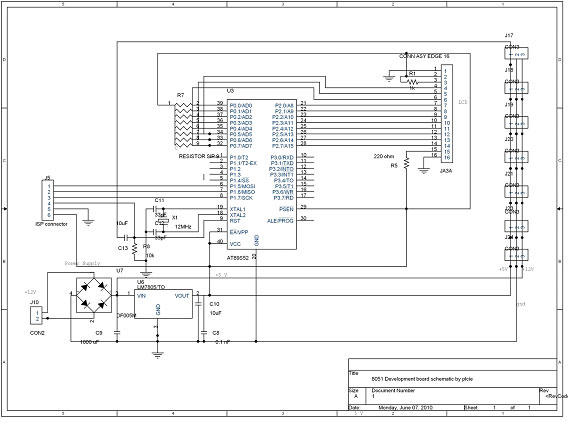
Atmel AVR and 8051 series ISP programmer

The ISP Programmer is designed to facilitate both in-system and standalone programming of Atmel ISP programmable devices, leveraging compatibility with existing STK200 hardware. The operational flexibility of this programmer is enhanced by its ability to interface with both 8051 and AVR series devices, making it a versatile tool for developers and engineers.
The circuit diagram of the in-system programmer highlights the necessity of using the 74HCT541 integrated circuit, which serves to isolate and buffer signals from the parallel port. This is particularly important for ensuring proper functionality with 3V parallel ports, which are increasingly prevalent in modern computing environments.
The standalone SPI programmer circuit emphasizes the use of a USB connection for power, which is a common and convenient method for powering programming devices. The modification of a standard USB cable to connect to the programmer is straightforward, with clear color coding for power connections. This design choice allows for easy integration into existing setups without the need for specialized power supplies.
Furthermore, the programmer's compatibility with various AVR series devices, including the 89S series and pin-compatible models, expands its usability. The option to create adapter boards for different pin configurations provides additional flexibility for users who may work with a range of devices.
The software component is well-structured, with specific instructions for different Windows operating systems, ensuring that users have a clear pathway to installation and operation. The inclusion of automatic hardware detection simplifies the setup process, although users must take care to configure the DB25 connector correctly to avoid issues.
The memory management aspect of the programming process is also noteworthy. The separation of code and EEPROM data within the memory buffer allows for organized programming, and the requirement for proper hex file formatting ensures that programming is executed smoothly without errors. The automatic erase function during programming is a valuable feature that streamlines the workflow, although users must be aware of the need to reset fuses to default settings when necessary.
In conclusion, the ISP Programmer presents a robust solution for programming Atmel ISP devices, combining ease of use with flexible configuration options. Its thoughtful design and comprehensive software support make it an essential tool for electronics engineers and developers engaged in embedded systems programming.This ISP Programmer can be used either for in-system programming or as a stand-alone spi programmer for Atmel ISP programmable devices. The programming interface is compatible to STK200 ISP programmer hardware so the users of STK200 can also use the software which can program both the 8051 and AVR series devices.
Figure 1 shows the circuit diagram of the in-system programmer interface, the power to the interface is provided by the target system. The 74HCT541 ic isolate and buffer the parallel port signals. It is necessary to use the HCT type ic in order to make sure the programmer should work with 3v type parallel port. Figure 2 shows the circuit diagram of the stand-alone spi programmer, the power to the interface is provided by the PC USB port which can supply a max of 100mA current.
Get a cheap USB cable, cut the cable other end connector and attach a crimp shell connector to this end, red wire is 5v and black is 0v. This programmer circuit can be use to program the 89S series devices and the AVR series devices which are pin compatible to 8051, like 90S8515.
For other AVR series devices the user can make an adapter board for 20, 28 and 40 pin devices. The pin numbers shown in brackets correspond to PC parallel port connector. The ISP-3v0. zip file contains the main program and the i/o port driver for windows 2000 & XP. Place all files in the same folder, for win-95/98 use the "ISP-Pgm3v0. exe" file, for win-2000 & XP use the "ISP-XP. bat" file. The main screen view of the program is shown in figure 3. Also make sure do not program the RSTDISBL fuse in ATmega8, ATtiny26 and ATtiny2313 otherwise further spi programming is disable and you will need a parallel programmer to enable the spi programming. For the fuses setting consult the datasheet of the respective device. For the auto hardware detection it is necessary to short pin 2 and 12 of DB25 connector, otherwise the software uses the default parallel port i.
e. LPT1. I have only included the devices which I have in hand, and verified their correct programming, when I will get the other devices the software will be updated. The memory buffer contains both the code data and the eeprom data for the devices which have eeprom memory.
The eeprom memory address in buffer is started after the code memory, so it is necessary the hex file should contains the eeprom start address after the end of code memory last address i. e. for 90S2313 the start address for eeprom memory is 0x800. The software does not provide the erase command because this function is performed automatically during device programming.
If you are required to erase the controller, first use the clear buffer command then program the controller, this will erase the controller and also set the AVR device fuses to default setting. 🔗 External reference
Related Circuits
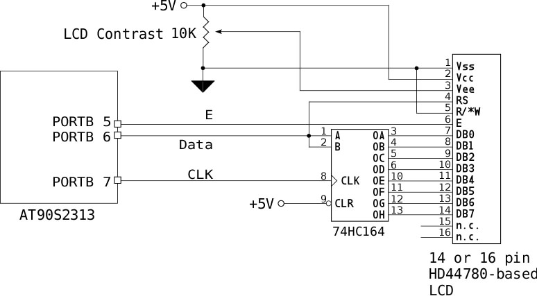
If no characters are displayed on the LCD and the hardware and software have been verified as functional, adjust the LCD Contrast potentiometer until the characters become visible. To send an 8-bit character or command to the LCD via...
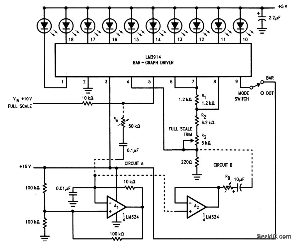
This circuit is an enhanced version of the display shown in Fig. 3-28, utilizing a triangular-wave oscillator. When the resistor RA is adjusted correctly, each incremental change in the input voltage (VIN) can be detected, allowing the glow from...
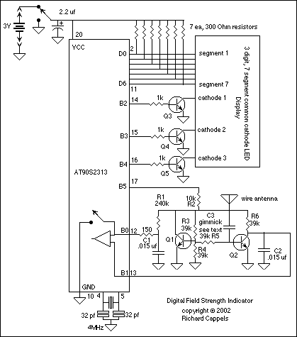
Useful as a transmitter tune-up meter or an RF sniffer, this is an RF field strength indicator that is loosely based on the Broad Band RF Field Strength Probe, described elsewhere. It detects RF via a square law detector,...
This article discusses the Gadgets, Gizmos, and Arduino (ATMega328). The content is straightforward and informative. The components mentioned in this article can enhance the understanding of the subject. For instance, readers can find and purchase components such as the...
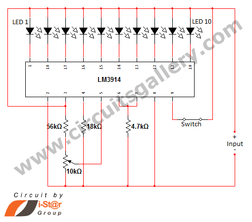
In various situations, it is necessary to indicate the amount of battery charge using methods such as LED dot displays or LED bar displays. This circuit utilizes the LM3914 integrated circuit to serve as a battery charge indicator with...
DTMF-based Robo Car design using the 8051 microcontroller project. This project demonstrates a method to control a domestic system using the DTMF tone generated by a telephone instrument when the user presses the keypad buttons of a mobile phone...