
LED dot display based Battery charge level indicator circuit diagram
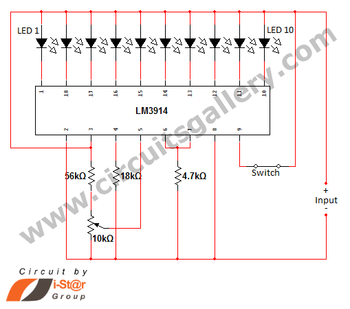
The battery charge indicator circuit based on the LM3914 integrated circuit is designed to provide a visual representation of battery voltage levels through LED displays. The circuit leverages the LM3914's ability to operate in two modes, dot mode and bar mode, allowing for flexibility in display preferences. In dot mode, each LED lights up sequentially based on the input voltage, while in bar mode, all LEDs light up simultaneously to represent the voltage level more prominently.
The calibration for a 12V battery involves configuring the circuit to ensure accurate voltage readings. The LM3914 can handle input voltages up to 25V, making it suitable for various applications beyond just 12V batteries. The external resistor connected to the IC allows for brightness adjustments, which can be useful in different lighting conditions or to save power.
The selection of operational modes is facilitated by a simple switch connected to pin 9. This feature enhances user interaction with the circuit, allowing for quick toggling between display modes depending on the user's preference or requirement. The removal of resistor R3 and the careful adjustment of the potentiometer are crucial steps in setting up the circuit for optimal performance.
In practical applications, this circuit can be implemented in various battery-powered devices where monitoring battery status is essential. It is particularly valuable in portable electronics, electric vehicles, and renewable energy systems, providing users with immediate feedback on battery health and charge levels. The design can be further customized for different voltage ranges by modifying the reference voltage and component values, ensuring versatility across multiple use cases.At many situations we need to display the amount of battery charge through some kind of indication methods like LED dot display or LED bar display. Here CG comes with a battery charge indicator circuit using LED dot display. This battery power level indicator circuit is build around LM3914 IC. It is able to sense voltage levels and is capable to d rive a display of 10 LEDs in dot mode or bar mode. We have already posted a temperature level sensor using this same IC (LM3914). This can also be used as a low battery voltage indicator circuit as it displays low voltage if you calibrate it to do so. Our circuit is most suitable for 12 volt battery status indication because we are calibrating it for 12V battery.
You can alter this DIY battery level indicator circuit for monitoring and displaying other voltages also. It is basically a milli volt measuring IC which is able to convert a varying milli volt input into a corresponding LED indication like a linear analog display.
The IC LM3914 can operate with a wide range of supply voltage (3V to 25V DC). We can control the brightness of LED by programming via an external resistor. The outputs pins of LM3914 are compatible for both TTL and CMOS. To select dot mode or bar graph mode a switch is given at the 9th pin. When switch is closed, pin 9 of the IC gets connected to the positive supply, then bar graph mode is enabled. For this just eliminate the resistor R3 and connect the high voltage (less than 25V) to the input and adjust the potentiometer until the 10th LED glows (in dot mode).
Now connect a low voltage at the input after removing high voltage. Then connect a high value potentiometer at the 4th pin, adjust it until LED1 glows alone. 🔗 External reference
Related Circuits
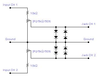
For simple electronic circuits, it may be sufficient to gain qualitative insights on dedicated electrical signals. This interface circuitry allows the line-in input of a standard PC sound card to be utilized as a 2-channel oscilloscope. Although this setup...
The above circuit is a precision voltage source and contains a temperature sensor with a negative temperature coefficient. Meaning, whenever the surrounding or battery temperature increases, the voltage will automatically decrease. The temperature coefficient for this circuit is -8mV...
Figures (a) and (b) illustrate two basic oscillator circuits operating at 2 MHz. The circuit design allows for adjustment of the optimal operating point through testing. The two oscillator circuits depicted in the figures utilize different configurations to achieve stable...

The ramp voltage from the low-frequency oscillator IC1 modulates IC2, thereby producing a rising and falling tone similar to the wail of police cars. The described circuit utilizes a low-frequency oscillator (IC1) to generate a ramp voltage. This ramp voltage...
If you need a timer circuit, we go after the most proven 555. However, if the delays are longer, based on timing capacitor capacity is too large. In this case, a circuit of Figure 1 After pressing the button...
This is a digital dice circuit that uses the PIC16C84. The digital dice circuit utilizing the PIC16C84 microcontroller is designed to simulate the random rolling of a standard six-sided die. The circuit operates by generating a random number between 1...