
AVR to LCD
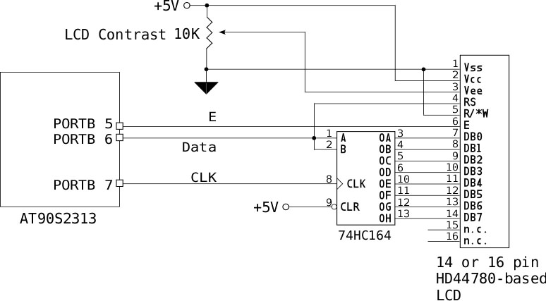
To implement the described functionality, a schematic can be constructed using the 74HC164 shift register connected to the AT90S2313 microcontroller and the HD44780 LCD. The microcontroller's PORTB will serve multiple functions: PORTB bit 6 will transmit the data (LCDDat) to the shift register, while bit 7 (LCDClk) will provide the clock signal for shifting the bits. The LCDE pin (PORTB pin 5) will control the enable signal for the LCD, ensuring that the data is read at the correct time.
The LCD's contrast is adjusted via a potentiometer, connected to the appropriate pin on the LCD to ensure visibility of the characters. The communication between the microcontroller and the LCD is managed through a bit-banging method, where the microcontroller manually controls the timing of the signals, which is particularly important given the HD44780's slower response time.
To ensure proper operation, the timing of the clock signals and the delays between data transmissions should be carefully calculated based on the specific clock frequency of the AT90S2313. The delays can be implemented using timer interrupts or busy-wait loops, depending on the desired efficiency and complexity of the code.
In summary, the design integrates a shift register to facilitate communication with the LCD, ensuring that the data is properly serialized and latched. The careful management of control signals and timing will lead to reliable performance of the LCD display in conjunction with the microcontroller.If you can`t see any characters displayed on the LCD (and you`ve checked that the hardware and software are working) turn the LCD Contrast pot until you can see the characters. To load an 8 bit character or LCD command into the 74HC164 shift register, the code shifts the byte out bit by bit through PORTB bit 6, (LCDDat) clocking the 74HC164 clockby toggling PORTB
bit 7 (LCDClk) for each bit. The data is latched on the rising edge of the clock, so the data bit on the port should be set first. Once the byte has been loaded into the shift register (and is now appearing on the LCD Data bus pins) the code selects the LCD register (either data or command) by setting the LCDDat pin low or high.
Since the LCDClk pin is not being toggled, the 74HC164 ignores this data. Once RS is set, the code toggles the LCD E clock (LCDE, PORTB pin 5) and the LCD reads the data on its data bus. The LCD will ignore all data on its data bus until its E clock is pulsed high, similar tothe Enable clock on many old 6800 and 6502 peripheral chips.
The AT90S2313 doesn`t have a fully functional SPI bus, but some other AVR parts do. You can use the SPI port on these devices to communicate with this circuit - with the appropriate changes in code. The HD44780 is a particularly slow device, so even though command and character bytes have to go through a serialization routine first, it`s still a good thing to add a delay between bytes sent.
The code assumes a 10MHZ AT90S2313 part; change the timing delays accordingly for different CPU clocks. I used Andyrate (which is no longer available) to calculate the timing values for the 8 bit timer used in the Delay routine.
Kevin Rosenberg has AVRCalc, which can be used instead to generate the timer values. 🔗 External reference
Related Circuits

An 8051 program must interact with external devices that facilitate communication with users. One of the most prevalent devices connected to an 8051 microcontroller is an LCD display. Common types of LCDs used with the 8051 include 16x2 and...
This project involves a USB interface for an alphanumeric LCD display, such as the 4x20 model, which can be controlled using the LCD Smartie program. The USB interface is implemented with the PIC18F2550 microcontroller and utilizes USB LCD modules....
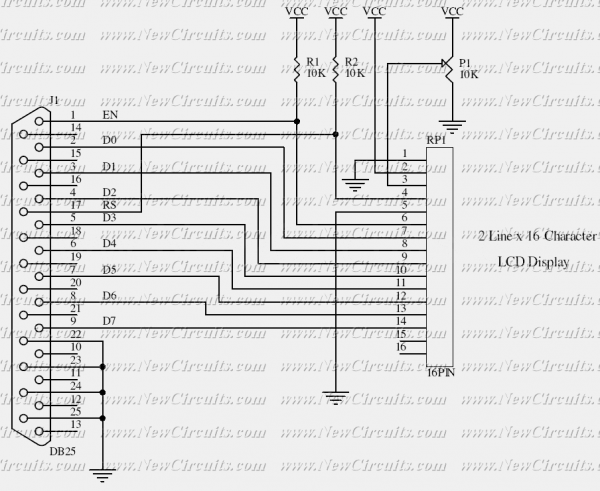
This simple circuit controls a popular 2-line x 16-character LCD by a PC via printer port. It doesn't use the Bi-directional feature found on newer printer ports, thus it should work with most, if not all, Parallel Ports. These...
This multimeter is designed to measure output voltage and current in a power supply unit (PSU), with the current sense shunt resistor connected in series with the load at the negative voltage rail. It operates using a single supply...
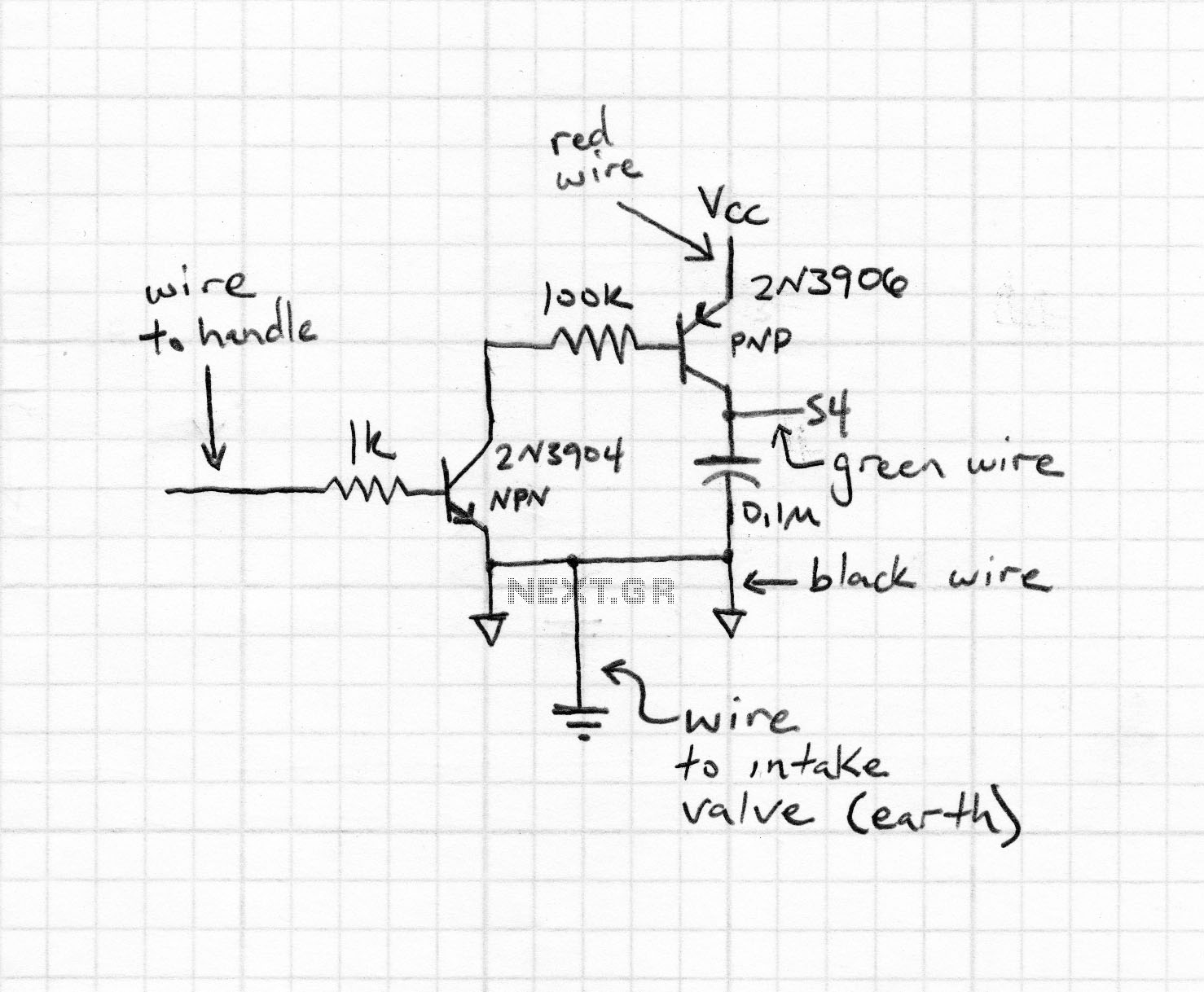
To drive a relay, a current greater than 20mA is required, which cannot be supplied by a single microcontroller pin. Therefore, a relay cannot be connected directly to a microcontroller pin. Instead, a simple amplifier circuit consisting of a...

If you are developing applications for the PIC MCU and miss debugging tools or don't have enough I/O pins for a parallel LCD interface in your design, this serial interface can help print debug messages and/or reduce the pin...
Warning: include(partials/cookie-banner.php): Failed to open stream: Permission denied in /var/www/html/nextgr/view-circuit.php on line 713
Warning: include(): Failed opening 'partials/cookie-banner.php' for inclusion (include_path='.:/usr/share/php') in /var/www/html/nextgr/view-circuit.php on line 713