
Attiny2313 based LAN cable tester

The RJ45 LAN cable tester designed by Vasilis Stergiopoulos is a practical tool for verifying the integrity and wiring configuration of Ethernet cables. The core of the circuit utilizes the Attiny2313 microcontroller, which is programmed to control the sequencing of LED indicators based on the connectivity of the cable. The device operates by connecting the cable under test between two connectors labeled A and B.
In a straightforward wiring scenario, the LEDs will illuminate in a predictable sequence, allowing users to confirm that the cable is wired correctly. The specific LED sequence for a straight-through connection is designed to provide a clear visual confirmation of each wire's continuity and proper termination.
In contrast, when a crossover cable is connected, the LED sequence will differ, illuminating in the order specified on the board. This feature is crucial for technicians who need to identify the type of cable quickly and ascertain whether it is functioning correctly.
The testing circuit also includes functionality to detect faults such as open circuits. If any LED fails to illuminate, it signals a problem in the corresponding wire within the cable, alerting the user to potential issues that may need to be addressed.
For scenarios where access to both ends of the cable is limited, the design incorporates a remote unit with only the B connector (B2). This allows testing to be performed from a single location, enhancing the convenience and applicability of the tester in various environments, such as in-wall installations or hard-to-reach areas.
Overall, the RJ45 LAN cable tester is a valuable device for network professionals, providing a reliable means of ensuring cable integrity and proper wiring configurations.Vasilis Stergiopoulos has built a RJ45 LAN cable tester. The circuit was originally designed to use a 555 and 4017 IC, but Vasilis has published the schematic and source code in assembly for using the Attiny2313 instead. The Attiny2313 produces successive outputs at port D, where the LAN-cable is connected. If a straight cable is connected between connectors A and B, then the LEDs will glow in successive order. If a cross cable is connected, then the glow order will be as noted on the board, i. e. 1, 2, 7, 4, 5, 8, 3, 6. If any other glow order occurs, it means that the cable is not wired correctly. If one or more LEDs don`t glow, then we have a corresponding open circuit. A remote unit with only the B connector (B2) can be used if both cable ends are not accessible in the same location. 🔗 External reference
Related Circuits
This circuit is based on the State Variable Band Pass Filter, incorporating amplitude-limited regenerative feedback. The State Variable Band Pass Filter (SVBPF) is a versatile filter design that allows for simultaneous control over the center frequency, bandwidth, and gain. This...
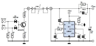
This circuit was designed to transmit commands over an LNB coaxial cable. An LNB (Low-Noise Block downconverter) is commonly used for satellite TV reception and is positioned at the focal point of a satellite dish. The circuit generates a...
The Implantable Lamp (A3024) is a radio-controlled lamp powered by a battery. Once encapsulated in epoxy and silicone, it is waterproof and compact, allowing it to be implanted in an animal. The A3024 can theoretically be activated by any...
This simple circuit employs a 741 operational amplifier (op-amp) in differential mode to function as a continuity tester. The voltage difference between the non-inverting and inverting inputs is amplified by the full open-loop gain of the op-amp. Initially, ignore...
Frequently, there are situations where the need arises to utilize a Zener diode, yet the operational voltage is unknown. Often, the characteristics or type inscribed on the diode are not legible. Zener diodes are essential components in electronic circuits, primarily...
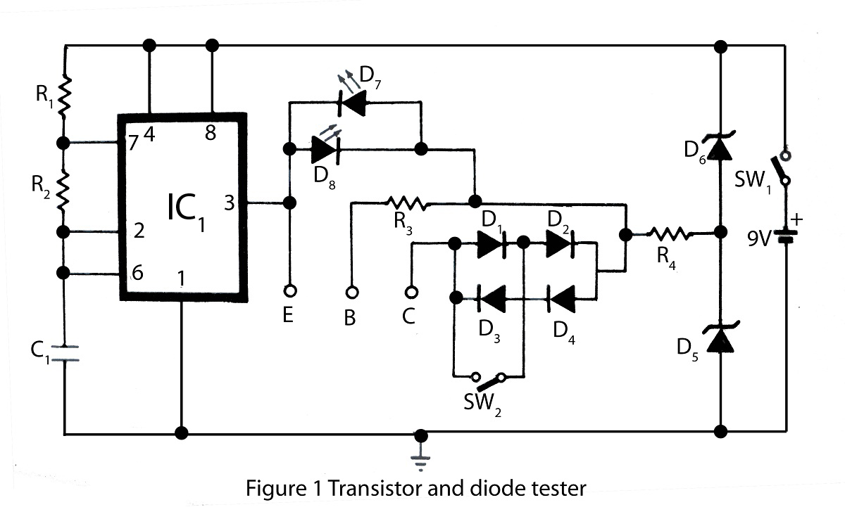
The transistor and diode tester available on this website is specifically designed for testing all types of transistors. Utilizing the principles of diode testing, it can also be used to check diodes. Various types of testing circuits can be...