
Implantable Lamp circuit project
In the ISL Conceptual Design, the L+ lead was proposed to be used as an antenna for command reception. However, this approach proved impractical. The input impedance of the tuning circuit is around 10 kΩ. To ensure that the 146-MHz power passes through the tuning circuit rather than into the lamp power supply, a 10-μH inductor with a self-resonant frequency of 150 MHz or higher is required on both the L+ and L− inputs. Such an inductor in a surface mount package is not available. The A3024 features two pads for a small loop antenna; one connects to the tuning circuit, while the other connects to circuit ground. This configuration allows for a peak response at nearly 146 MHz, using component values consistent with calculations. However, the observed peak voltage is only 65 mV, despite efforts to optimize the antennas for maximum signal. Without the tuner, a voltage of 120 mV was recorded at 146 MHz.
Attempts to activate the lamp using the antenna of an A3019E showed no indication of transmission in the voltage reading. The signal induced by the A3019E was measured to be less than 2 mV, insufficient to turn on the lamp. Reception range tests were conducted with the same antenna orientations and power levels. The lamp flashed at a range of 12 cm with the tuning circuit in place, 13 cm without it, and 17 cm when the extension circuit was removed, a BR1225 battery was loaded, and the tuning circuit was omitted. After modifications, the A3024 was designated as A3024Y, which has no tuning circuit. A 1/2-wave antenna and booster amplifier were utilized to maximize 146 MHz power transmission. By pulsing RF power for 5 ms out of every 50 ms, it was estimated that reception reliability was at least 95% at ranges of 50 cm or less after approximately ten minutes of movement. When the tuning circuit was reintroduced, reception reliability decreased to 80% at 50 cm. Upon removing the tuning circuits, reception improved to over 95%.
This detailed analysis of the A3024's operation emphasizes the challenges encountered in radio frequency signal reception and the optimization of antenna configurations for effective command activation of the implantable lamp.The Implantable Lamp (A3024) is a radio-controlled lamp powered by a battery. Once encapsulated in epoxy and silicone, it is water-proof and compact, so so that it may be implanted in an animal. The A3024 can, in theory, be activated by any sufficiently-powerful source of radio waves. But we plan to activate the A3024 with the Command Transmitter (A3023CT), which produces 146-MHz radio waves.
Thus the tuning circuit shown in the S3024 circuit diagram is designed to select power in the neighborhood of 146 MHz. The A3024 is useful in its own right as an implantable source of optical stimulation for gene therapy.
It is intended, however, to test the command reception, lamp power generation, and light delivery of the Implantable Sensor with Lamp (ISL). The A3024 provides 5-V power to an LED through its L+ and L− pads. These must be connected to two leads with resistance suitable for driving the lamp with 5 V. If the forward voltage drop of the LED is 3.1 V and we want 20 mA current, the lead resistance should be around 100 Ω.
In the ISL Conceptual Design, we proposed to use the L+ lead as an antenna for command reception. But this turns out to be impractical. The input impedance of our tuning circuit is around 10 kΩ. In order to force 146-MHz power to pass through the tuning circuit rather than into the lamp power supply, we would need a 10-μH inductor with self-resonant frequency 150 MHz or higher on both the L+ and the L− inputs. We can't find such an inductor in a surface mount package. The A3024 provides two pads for a small loop antenna. One is connected to the tuning circuit, the other to the circuit ground. Now we see a peak response at almost exactly 146 MHz, and using component values that agree with our calculations.
But we note that the peak voltage is only 65 mV, and this is after we fiddle with the antennas to get the biggest signal. We obtained 120 mV at 146 MHz with not fiddling when we had no tuner. We try again to activate the lamp with the antenna of an A3019E. We see no sign of the A3019E transmission in VR. Whatever signal the A3019E induces is less than 2 mV. The lamp will not turn on. We measure reception range for the same antenna orientations and power. We see the lamp flashing at range 12 cm with our tuning circuit in place, 13 cm with the tuning circuit removed, and 17 cm when we cut off the extension circuit, load a BR1225 battery, and leave off the tuning circuit.
[17-JAN-13] After clipping off the extension and loading a battery onto our A3024, we have an A3024Y. It has no tuning circuit. We use our 1/2-wave antenna and booster amplifier to provide as much 146 MHz power as we can. We attach the circuit to the end of a stick and pulse the RF power for 5 ms out of every 50 ms. After about ten minutes of moving around, we estimate that reception is at least 95% reliable at ranges 50 cm and less.
We load the tuning circuit and repeat our movements. Reception is now only 80% at 50 cm. We remove the tuning circuits. Reception jumps back up to over 95%.
Related Circuits
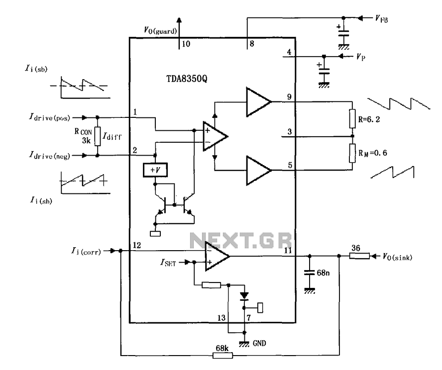
The TDA8350Q test circuit includes a push-pull amplifier configuration where the output terminal resistor serves as a dummy load for testing an alternative deflection coil. The TDA8350Q is a high-performance integrated circuit designed for use in television and display systems....
This low noise audio power supply circuit can reduce noise and ripple voltage by 40 dB over the 100 Hz to 20 kHz audio range. In portable applications such as... This low noise audio power supply circuit is designed to...
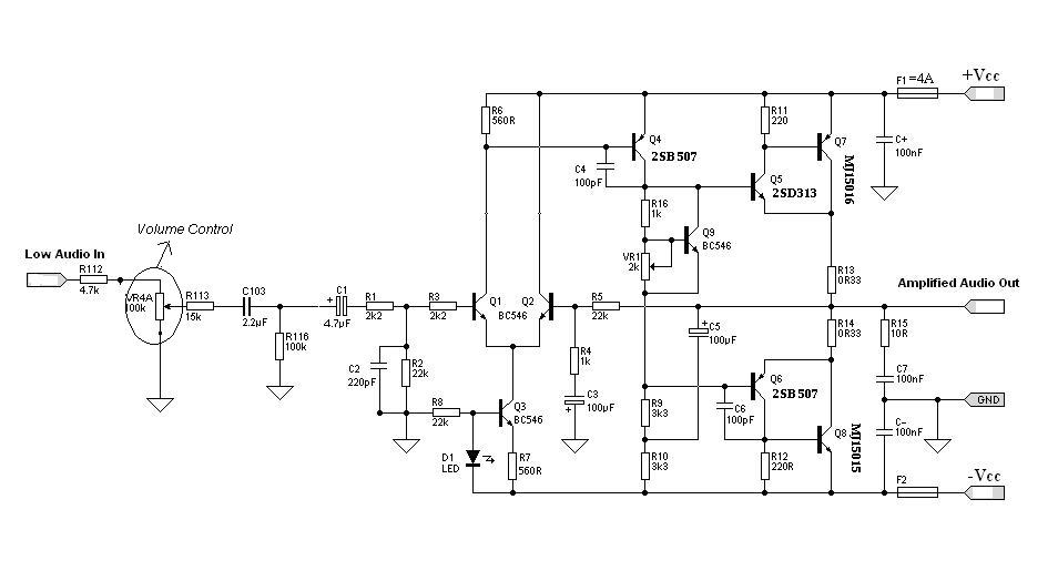
Designing an audio amplifier from scratch using discrete components is an engaging task, as it enables users to create amplifiers that meet diverse requirements. Audio amplifiers can enhance low-level sounds from mobile devices, making them louder and more vibrant....
%2BCircuit%2Bdiagram%2Busing%2BCD4047%2Band%2BIRFZ44%2Bpower%2BMOSFET.png)
This simple low-power DC to AC inverter circuit converts 12V DC to either 230V or 110V AC. By making simple modifications, it is also possible to convert 6V DC to 230V AC or 110V AC. This inverter can be...
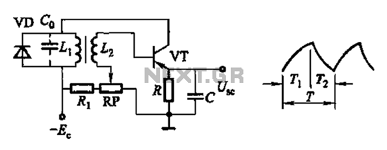
Common non-sinusoidal oscillator circuit, waveform and frequency formula - pulse wave oscillator - single-junction transistor blocking oscillator. The common non-sinusoidal oscillator circuit described is a pulse wave oscillator that utilizes a single-junction transistor in a blocking configuration. This type of...
This article discusses a fully automatic 6V 4.5AH battery charger circuit that utilizes the LM317T integrated circuit along with a few additional components. The circuit is designed to charge a 6V lead-acid battery. The circuit utilizes the LM317T voltage regulator,...
Warning: include(partials/cookie-banner.php): Failed to open stream: Permission denied in /var/www/html/nextgr/view-circuit.php on line 713
Warning: include(): Failed opening 'partials/cookie-banner.php' for inclusion (include_path='.:/usr/share/php') in /var/www/html/nextgr/view-circuit.php on line 713