
ATV Repeater System Exciter
The RTX-70 exciter system's architecture is structured to ensure optimal performance in transmitting audio and video signals for ATV applications. The integration of the Hamtronics TA451 transmitters allows for high fidelity and reliable transmission, which is crucial for maintaining signal integrity across varying distances and environmental conditions. The use of a diplexer to combine the outputs of the two exciters minimizes loss and ensures that both the visual and aural signals are transmitted efficiently.
The audio processing chain is designed to enhance the quality of the transmitted signal, employing sophisticated filtering and amplification techniques to manage audio levels effectively. The automatic level control circuit is particularly noteworthy, as it adapts to fluctuations in audio input, thereby preventing distortion and ensuring clarity in transmission. The design considerations taken to compensate for temperature variations further highlight the system's robustness, as they mitigate potential issues that could arise from environmental changes.
This exciter system's versatility in audio transmission methods allows for adaptability in various operational scenarios, catering to both standard and specialized audio reception equipment. The ability to switch between sub-carrier and on-carrier audio transmission enhances the system's usability, making it suitable for a wide range of applications within amateur radio and commercial broadcasting. Overall, the RTX-70 exciter represents a well-engineered solution for ATV transmission, combining advanced technology with practical design considerations to meet the demands of modern communication systems.A model RTX-70 exciter that was originally used in the Brookdale ATV Repeater System. This page describes some the design considerations and new features possible with this new exciter, and includes schematics of the circuits designed during the exciter`s development. The ATV exciter described here uses a pair of Hamtronics model TA451 2-watt narrow-band FM voice transmitters
to develop video and audio carriers on 439. 250 MHz and 443. 750 MHz. The TA451 is a single board, phase modulated exciter designed for commercial two-way land-mobile as well as amateur radio service. Several circuit modifications were made to each exciter to permit their use in this application. In operation, one TA451 exciter is operated at 439. 250 MHz and is amplitude modulated with video information, while the second operates on 443. 750 MHz and is frequency modulated to produce a broadcast-standard FM aural subcarrier. The RF output of each exciter is combined in a diplexer and further amplified through several linear power amplifier stages.
Figure 1 shows the audio circuitry used to produce high-quality frequency modulation from each exciter. Line-level audio from the repeater controller is fed through a 15 kHz active low-pass filter (U1A), a 75 microsecond pre-emphasis network (R8, C5), and an automatic level control circuit (U1B).
Automatic level control is used to prevent over modulation should the audio input to the exciter rise above normal levels. This method of level control generates considerably less harmonic distortion than audio clippers typically found in FM voice and some commercial ATV transmitters.
Audio signal levels of 20 times above normal can be handled with this circuit without causing overmodulation or excessive distortion. Audio is then fed through a pair of voltage amplifiers having different gains and opposite phase shifts (U1C, U1D).
Each amplifier drives a varactor diode that is connected in series with an inductor and crystal in each TA451 exciter, thereby allowing direct frequency modulation of the RF carrier. A DC bias voltage produced by voltage regulator U3 and its associated circuitry is applied to each varactor along with the transmitted audio.
This bias voltage is temperature compensated by diodes D6 and D7 to minimize frequency drift that would occur due to the varactor`s temperature sensitivity. Since the TA451 exciters are virtually identical to one another, any drift that might occur due to temperature variations will be proportional in both units.
This maintains a very accurate 4. 5 MHz separation between the visual and aural carriers regardless if any drift due to temperature changes should occur. The ATV exciter described here can transmit audio in a variety of ways including broadcast standard sub-carrier audio, "on-carrier audio", or a combination of both methods.
Sub-carrier audio is produced by frequency modulating the TA451 operating at on the audio sub-carrier frequency with a peak deviation +/- 25 kHz. On-carrier audio is produced by frequency modulating the video carrier with a deviation of +/- 5 kHz.
On-carrier audio allows reception of ATV signals by tuning to the video carrier frequency (439. 250 MHz) with narrow-band FM receiver, such as a handheld UHF-FM receiver or scanner. A combination of both audio transmission methods is also possible with this exciter, allowing the greatest flexibility in ATV audio reception. When the combination is used, the frequency modulation fed to each exciter is done in opposite phase, and the deviation of the audio sub-carrier is reduced from 25 kHz down to 20 kHz.
A standard television receiver will detect FM inter-carrier audio as the difference between the visual and aural carriers. Since both are frequency modulated and are modulated in opposite directions, the receiver se 🔗 External reference
Related Circuits
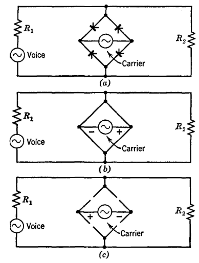
The Type C system was first installed around 1925 and has been extensively utilized since then. It incorporates the most desirable features of previously considered systems. Similar to the Type A system, the carrier signal is suppressed, minimizing the...
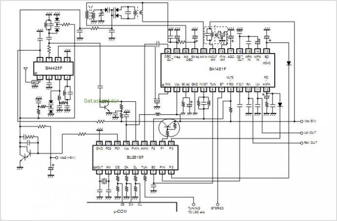
The BA3822LS, BA3822FS, BA3823LS, and BA3824LS are monolithic, five-point stereo graphic equalizer integrated circuits (ICs). Each IC features two channels, with five center frequencies for each channel that can be independently set using external capacitors. These ICs support a...
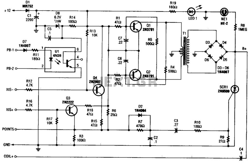
At the core of the CD4-MX is an astable multivibrator, constructed using transistors Q1 and Q2, which drives step-up transformer T1. The output from T1 is rectified by diodes D3 to D6 and utilized to charge capacitor C4. Upon...
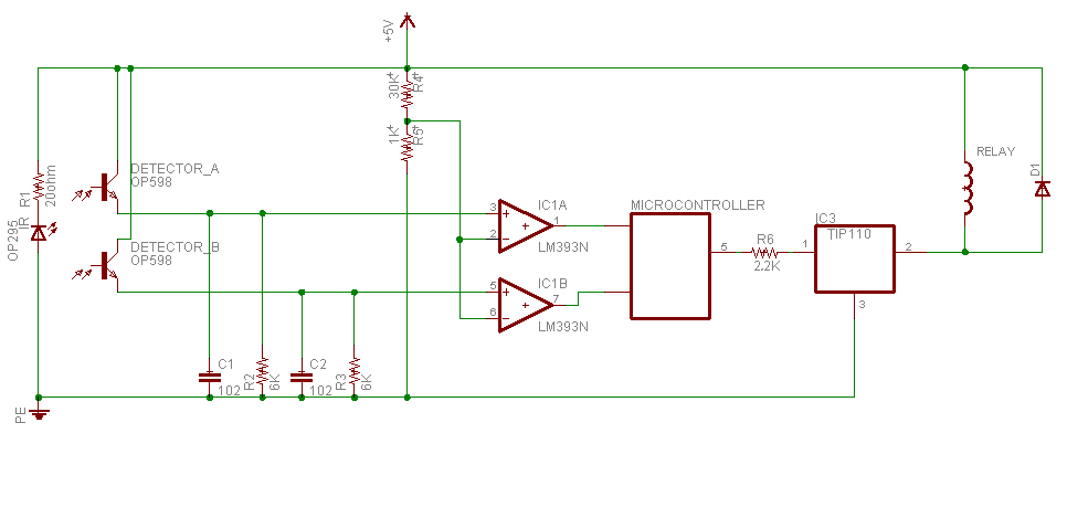
Sensing unit consists of infrared emitter OP295 to produce the infrared beam, and two detectors in front of the emitter to detect the infrared beam OP598. Since the main idea in this device is to know person direction; and...
The color wheel and motor control are customizable. This system utilizes field-sequential color rather than the "compatible color" introduced later. Following the wiring modifications, further details about the color wheel will be provided. Without the wheel, CBS shows can...
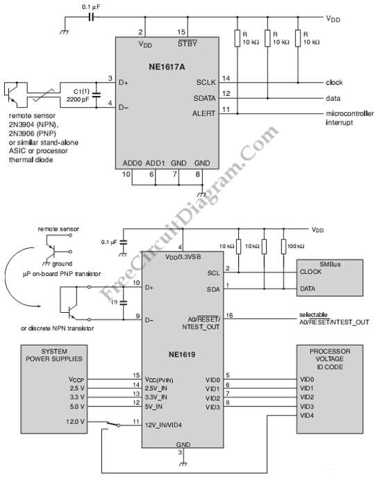
This is a circuit of a board system monitoring the temperature and voltage conditions. It uses the NE1617A, which is a 2-channel temperature sensor. The described circuit serves as a monitoring system for both temperature and voltage conditions, utilizing the...