
Type C Carrier Telephone Systems
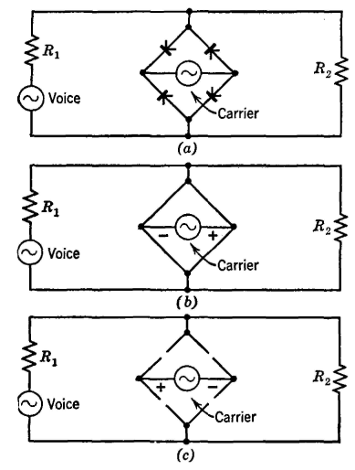
Modulation in the Original Type C Systems: As previously discussed, sidebands containing the transmitted information are generated in the modulator. A modulator is defined as a device that facilitates the modulation process. It may operate based on non-linear characteristics or controlled variations of circuit quantities. In the original Type C carrier system, the non-linear relationship between grid voltage and plate current in triode thermionic vacuum tubes was utilized for modulation. To achieve this, the speech signals intended for transmission and the carrier frequency are simultaneously applied to the grids of the tubes.
The original Type C carrier telephone system represents a significant advancement in telecommunications, effectively utilizing modulation techniques to enhance signal transmission quality. The suppression of the carrier signal minimizes line attenuation, while the use of separate frequencies for transmitting and receiving ensures efficient communication. The incorporation of advanced filtering techniques allows for the clear separation of voice and carrier signals, facilitating reliable transmission over long distances. The modifications made in 1938 reflect the system's adaptability to new technologies, ensuring its continued relevance in the evolving landscape of telecommunications. Each component within the system, from the balanced modulator to the directional filters, plays a crucial role in maintaining the integrity and clarity of the transmitted audio signals. The pilot channel serves as an essential tool for monitoring signal strength, further enhancing the system's reliability. Overall, the original Type C carrier telephone system exemplifies the effective integration of various electronic components and principles to achieve high-quality communication.The type C system was first installed about 1925 and has been very extensively used. It incorporates the most desirable features of the systems just considered. Like the type A system, the carrier is suppressed, and hence the effect of line attenuation is minimized. Like the type B, different frequencies are used for transmitting and receiving, an d filters, instead of carrier-frequency hybrid coils, are used to separate the talking and the receiving signals. The original type C carrier telephone system was extensively modified about 1938 to take advantage of developments in communication.
Original Type C Carrier Telephone System. 30 The schematic diagram of the original type C carrier is shown in Fig. 20. To explain the operation of this system, assume that a person whose telephone is connected to channel 1 at the left is speaking to a person whose telephone is connected to channel 1 at the right. The incoming speech signals pass through the voice-frequency hybrid coil, and to the modulator at the top.
This is a balanced modulator (page 421) that eliminates the carrier but produces both sidebands. The band filter selects one sideband and rejects the other. The selected sideband passes down to the common wires leading to the transmitting amplifier, where all the incoming signals to be transmitted are amplified to the proper level for impressing on the line. The amplified signals from the three channels pass through the high-pass filter and hence to the line.
Each of the three modulators is fed with a different carrier frequency, and hence each of the three sidebands that are transmitted simultaneously is at a different frequency as Fig. 18 shows. Figure 20. Schematic diagram of original type C carrier telephone system, and of carrier and voice-frequency equipment at a repeater station.
(Reference 30. ) At a repeater point the carrier frequencies are separated from the voice frequencies by the high-pass and low-pass filters. At the carrier amplifier the transmitting and the receiving signals are separated by directional filters.
The equalizer functions as explained on page 410 The sideband signals of the three channels are amplified in the "west to east" amplifier, 30 pass through the directional filter, the high-pass filter, and the amplified signals are then impressed on the line toward the "east terminal" at the right of Fig. 20. At the east terminal the received sidebands from the transmitting "west terminal" are passed by the high-pass line filter upward to the directional filters.
Since the east terminal now is being considered as receiving from the west terminal, the three incoming sidebands will pass through the lower directional filter and to the common circuit leading to the demodulating apparatus. The sideband from channel 1 will be passed by the band-pass filter of channel 1 to the demodulator (page 421).
The output of the demodulator will contain the original message at audio frequencies, and this is passed by the voice-frequency hybrid coil to the telephone set of the listener. Channels 2 and 3 function in a manner similar to that just explained. The pilot channel noted on Fig. 20 is for monitoring and adjusting the transmission to ensure that the signal strength is correct at all times.
30 Modulation in the Original Type C Systems. 30 As discussed in the preceding paragraphs, sidebands, which contain the information to be transmitted, are created in the modulator. A modulator is defined 1 as "a device to effect the process of modulation. It may be operated by virtue of some non-linear characteristic, or by a controlled variation of some circuit quantity.
" In the original type C carrier system the non-linear relation between grid voltage and plate current in triode thermionic vacuum tubes was used to produce modulation. To accomplish this, the speech signals to be transmitted and the carrier frequency are impressed simultaneously on the grids of tubes
🔗 External reference
Related Circuits
In order to achieve a status between two levels of switching for two calls at the same time, you must first establish privacy on each call. Otherwise, you will end up with all four phones talking to each other,...
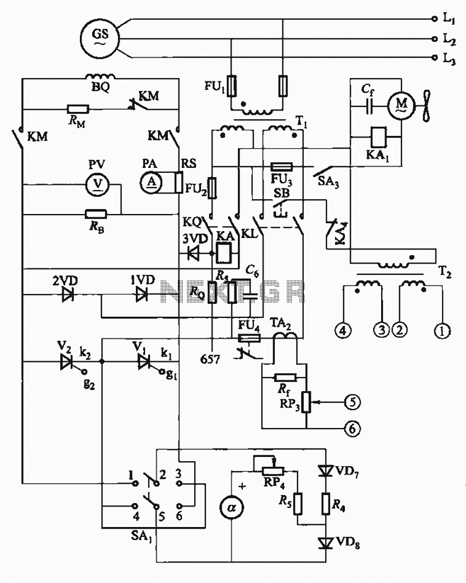
The FKL-32 type automatic thyristor excitation device is designed for synchronous generators with a terminal voltage of 400V and a capacity of 500kW or below. It is used for the automatic adjustment of excitation. The FKL-32 automatic thyristor excitation device...
A long time ago, when telephones were simple and reliable from an electrical standpoint, telecom operators installed surge protection on all telephone lines exposed to storm risks. Paradoxically, with the advent of delicate and expensive equipment such as electronic...
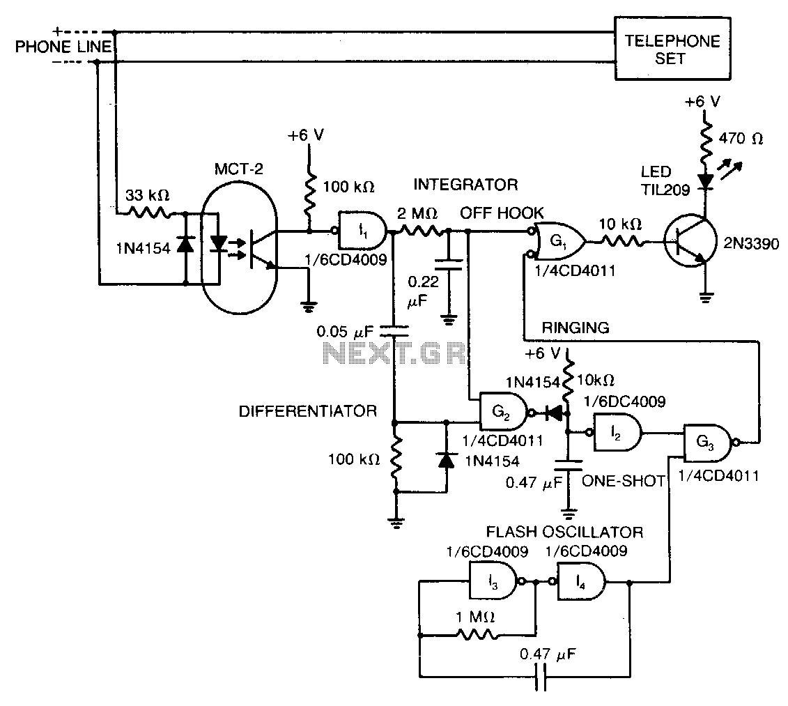
The LED signifies the status of a remote telephone. The light remains off when the phone is hung up. It emits a steady glow when the phone is off the hook, and it flashes intermittently while the phone is...
This version of the Link uses DTMF tones for dialing both internally between handsets, and externally for outside calls. Remember, in some countries, it is ILLEGAL to simply connect unapproved and untested equipment to Telco lines, so avoid the...
The PE014A12 relay from Tyco Electronics features a single coil that requires a positive voltage to activate and a negative voltage to deactivate. The PE014A12 relay is a single-coil electromagnetic relay designed for applications requiring a simple on/off switching mechanism....