
Board System Monitoring for Temperature and Voltage Condition
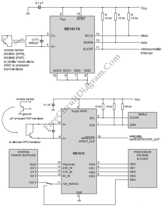
The described circuit serves as a monitoring system for both temperature and voltage conditions, utilizing the NE1617A integrated circuit. The NE1617A is designed to provide accurate temperature readings from two separate channels, making it suitable for applications where temperature monitoring is critical.
In this circuit, the NE1617A interfaces with a microcontroller or a microprocessor, enabling the collection of temperature data for further processing or display. The output from the NE1617A can be in the form of analog voltage levels or digital signals, depending on the specific configuration and requirements of the application.
Additionally, the circuit may include voltage monitoring capabilities, which can be achieved by integrating voltage sensors or comparators that provide feedback on the supply voltage levels. This feature ensures that the system can operate within specified voltage ranges and can trigger alarms or corrective actions if voltage levels fall outside acceptable limits.
The overall design may incorporate various components such as resistors, capacitors, and possibly operational amplifiers to filter noise and stabilize the readings from the temperature sensor. Furthermore, the circuit could utilize a power supply management system to ensure that the NE1617A and associated components receive a stable voltage supply.
In summary, the circuit is a comprehensive solution for monitoring temperature and voltage conditions using the NE1617A, making it suitable for a wide range of applications in industrial, automotive, or consumer electronics sectors.This is a circuit of board system monitoring for temperature and voltage condition. It uses the NE1617A. The NE1617A is a 2 channel temperature sensor. It can. 🔗 External reference
Related Circuits
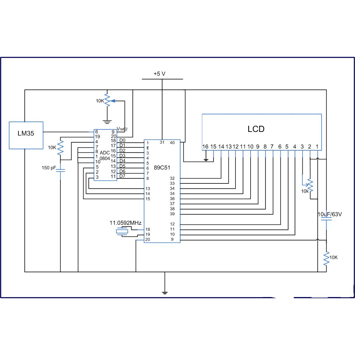
The LM35 series are precision integrated-circuit temperature sensors, whose output voltage is linearly proportional to the Celsius (Centigrade) temperature. The LM35 has an advantage over linear temperature sensors calibrated in Kelvin, as the user is not required to subtract...
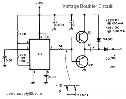
The schematic diagram originates from a 12V DC voltage doubler circuit power supply. This circuit diagram illustrates a DC voltage doubler/DC converter that transforms a 12V DC power supply into 24V DC and 18V DC outputs. It is compatible...
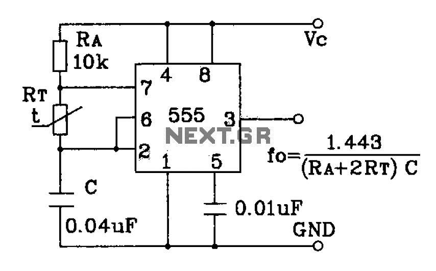
555 precision temperature sensor with temperature frequency converting circuit diagram consisting of: The 555 precision temperature sensor operates by converting temperature variations into frequency signals. This circuit typically utilizes a 555 timer IC configured in astable mode to generate...
A DC-to-DC step-up converter is typically implemented using a transformer, which converts DC voltage to AC voltage, steps it up with the transformer, and then rectifies and filters the output to achieve a higher DC voltage. However, a voltage...
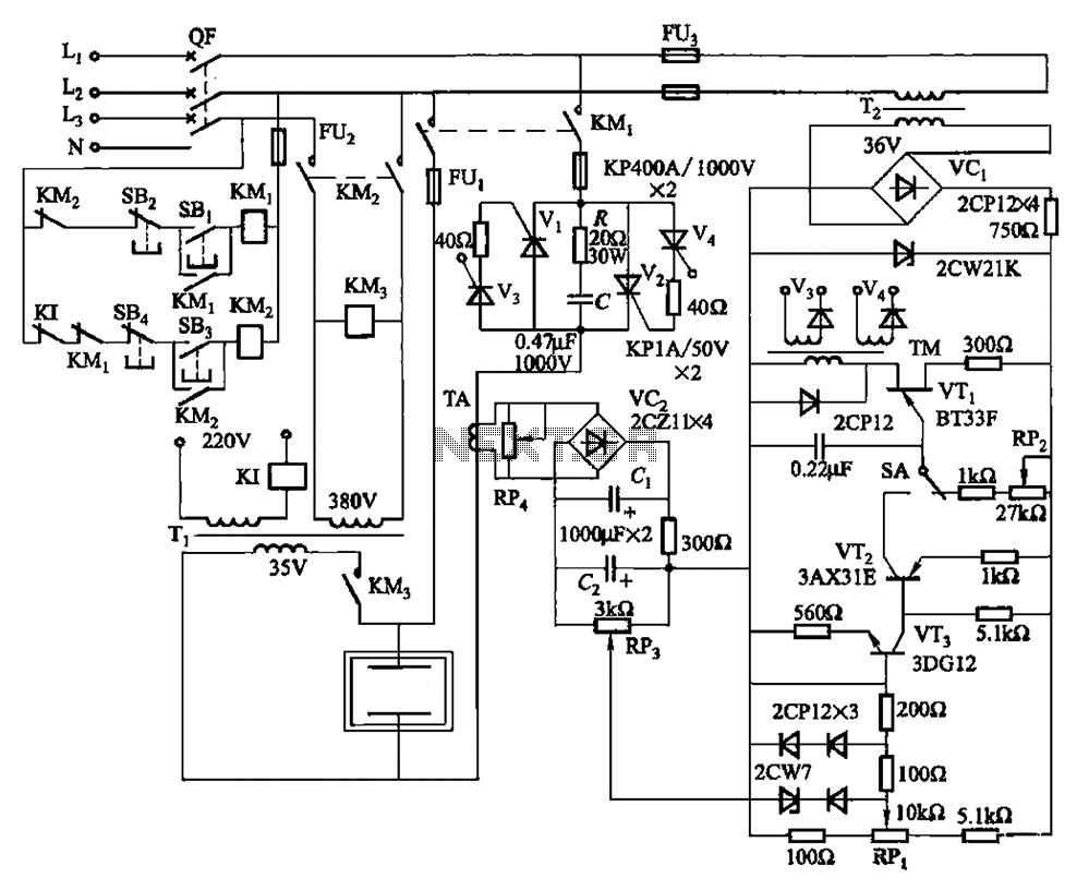
80 kW resistance salt bath furnace control circuit. The salt bath resistance furnace is a high-power device that employs fast start and temperature control technology to significantly save energy. The circuit includes a single-junction transistor (VTi) used as a...
This is a circuit for a Voltage-to-Pulse Duration Converter. The circuit is designed to convert voltage into pulse duration by integrating a timer IC and an operational amplifier (OP Amp). The Voltage-to-Pulse Duration Converter circuit utilizes a timer IC, typically...