
Audible Logic Probe
The NE556 timer is a dual timer IC that can operate in various configurations, including monostable and astable modes. In the context of an audible logic probe, it is primarily used in a monostable configuration to generate a sound signal when a specific logic level is detected at the terminal under test.
To implement this circuit, the NE556 is connected to a speaker or piezo buzzer, which will produce sound when a high or low logic level is sensed. The circuit can include a resistor and capacitor connected to the trigger pin of the NE556 to define the output pulse width, allowing the user to adjust the duration of the sound produced.
The input terminal of the probe is connected to the logic circuit being tested. When the terminal is at a high logic state (typically close to the supply voltage), the NE556 is triggered, causing the output to go high and activating the buzzer. Conversely, when the terminal is at a low logic state (ground level), the output remains low, and the buzzer remains silent.
Additional components such as diodes can be included to protect the circuit from voltage spikes, and a potentiometer may be added to allow for volume control of the audible output. This circuit provides a practical solution for testing digital logic states without the need for visual indicators, making it a valuable tool for engineers and technicians in the field of electronics.We can use NE556 timer IC to make indication of static of terminal in digital logic audible.? Audible logic probe can be very useful when we have to visually. 🔗 External reference
Related Circuits
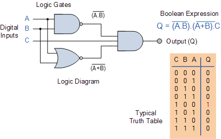
Electronics tutorial on combinational logic circuits that utilize logic gates to create multiplexers, encoders, and solid-state switches. Combinational logic circuits are fundamental components in digital electronics, characterized by their ability to produce outputs based solely on the current inputs, without...
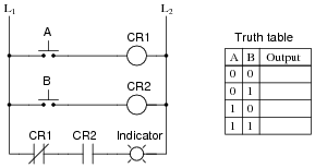
In ladder logic symbolism, an electromechanical relay coil is depicted as a circle, while the contact(s) actuated by the coil are represented by two parallel lines, resembling a capacitor symbol. To interpret a ladder logic diagram, it is essential...
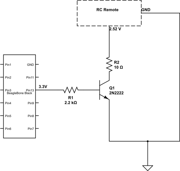
The remote control of an RC car was modified by extending wires from the backward, forward, left, and right switches. Grounding any of these wires completes the circuit and sends a signal to the car. The intention is to...
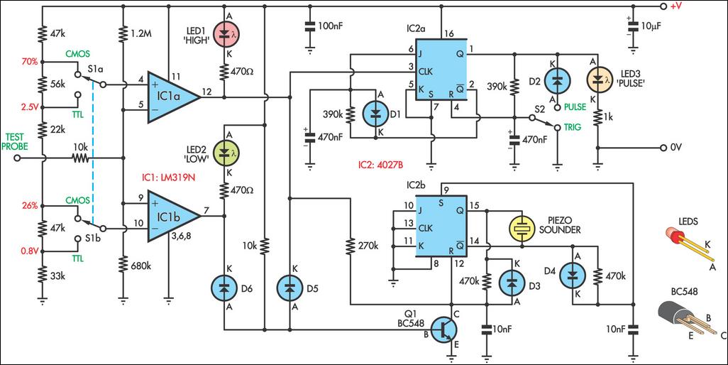
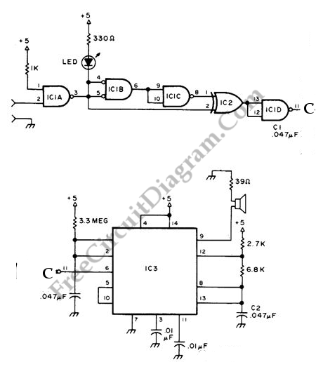
This logic probe can be configured to operate on either TTL or CMOS logic levels using switch S1. A series of resistors connected to switch S1 establishes the threshold levels for a window comparator made up of IC1a and...

This circuit diagram represents a logic probe based on a single CMOS integrated circuit (IC). The logic probe indicates three conditions: High, Low, and Pulsing. Additionally, no LEDs will illuminate when the probe input is in a high-impedance state,...
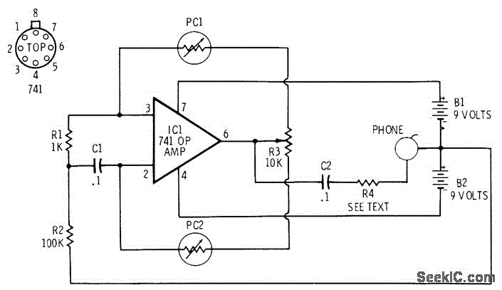
The 741 operational amplifier is configured as an audio oscillator utilizing Radio Shack 276-677 photocells within the feedback circuit. When light illuminates PC1, its resistance diminishes, leading to a corresponding decrease in the frequency of the audio tone heard...