
Electromechanical relay logic

There is an issue in the relay logic circuit where Lamp 2 operates correctly, but Lamp 1 does not turn on. Possible failures in the circuit must be identified, and an efficient troubleshooting method should be employed to minimize electrical measurements needed to isolate the problem. This scenario is suitable for in-class discussions. Several factors could contribute to Lamp 1 never energizing. When explaining the measurements taken to isolate the problem, it is crucial to mention whether the pushbutton switches are being actuated during those measurements. Sufficient classroom time should be allocated for discussing troubleshooting techniques, as electrical troubleshooting is a skill that requires development and practice.
A common application of electromechanical relay logic is in motor control circuitry. A simple DC motor control ladder diagram illustrates a momentary pushbutton switch that starts the motor and another switch that stops it. This circuit allows students to analyze a simple latch, a system that retains the state of prior switch actuations (either set or reset; latched or unlatched). A straightforward motor start/stop circuit serves as an introductory example of latch circuits. The structured nature of ladder diagrams contrasts sharply with the complexity of real motor control circuits, making them invaluable for troubleshooting.
To help students familiarize themselves with standard switch contact configurations, practice with identification and truth tables is recommended. Recognizing ladder logic sub-circuits at a glance is essential for analyzing more complex relay circuits that utilize them.
In the context of troubleshooting Lamp 1, it is vital to consider the entire circuit path. Begin by verifying the functionality of the pushbutton switches and ensuring they are properly connected. Measure the voltage across the relay coil to confirm that it is receiving power when the corresponding pushbutton is actuated. If the coil is energized, check the relay contacts for continuity to ensure they are closing properly. If Lamp 1 still does not illuminate, inspect the wiring and connections leading to the lamp itself, as well as the lamp's integrity. This systematic approach minimizes unnecessary measurements and leverages observational skills to identify faults effectively.In ladder logic symbolism, an electromechanical relay coil is shown as a circle, and the contact(s) actuated by the coil as two parallel lines, almost like a capacitor symbol. Given this knowledge, interpret the following ladder logic diagram: How do we know which relay contact is actuated by which relay coil How does this convention differ fromthat of standard electrical/electronic schematic
diagrams, where the relay coil is shown as an actual coil of wire (inductor symbol) with the contact "linked" to the coil by a dashed line Also, what type of logic function behavior (AND, OR, NAND, or NOR) does the above circuit exhibit In ladder logic diagrams, relay coils are associated with their respective contacts by name rather than by proximity. In this particular circuit, the logic function represented is the AND function. Many students find it confusing that relay contacts and coils need not be drawn next to one another in a ladder logic diagram, because it is so different from the schematic diagrams they are accustomed to.
The non-necessity of proximity in a ladder logic diagram does have its advantages, though! It is simply a matter of getting used to a new way of drawing things. There is a problem somewhere in this relay logic circuit. Lamp 2 operates exactly as it should, but lamp 1 never turns on. Identify all possible failures in the circuit that could cause this problem, and then explain how you would troubleshoot the problem as efficiently as possible (taking the least amount of electrical measurements to identify the specific problem). This is a problem worthy of a good in-class discussion with your peers! Of course, several things could be wrong in this circuit to cause lamp 1 to never energize. When you explain what measurements you would take in isolating the problem, be sure to describe whether or not you are actuating either of the pushbutton switches when you take those measurements.
Be sure to leave plenty of classroom time for a discussion on troubleshooting this circuit. Electrical troubleshooting is a difficult-to-develop skill, and it takes lots of time for some people to acquire. Being one of the most valuable skills a technical person can possess, it is well worth the time invested!
The challenge question is very practical. Too many times I have seen students take meter measurements when their other senses provide enough data to render that step unnecessary. While there is nothing wrong with using your meter to confirm a suspicion, the best troubleshooters use all their senses (safely, of course) in the isolation of system faults.
A very common application of electromechanical relay logic is motor control circuitry. Here is a ladder diagram for a simple DC motor control, where a momentary pushbutton switch starts the motor, and another pushbutton switch stops the motor: This circuit provides students with an opportunity to analyze a simple latch: a system that "remembers" prior switch actuations by holding a G tate" (either set or reset; latched or unlatched). A simple motor start/stop circuit such as this is about as simple as latch circuits get. Students should be able to immediately comprehend the benefit of using nice, neat, structured ladder diagrams when they see the tangled mess of wires in a real motor control circuit.
And this is not even a complex motor control circuit! It takes very little imagination to think of something even uglier than this, and what a task it would be to troubleshoot such a circuit without the benefit of a ladder diagram for guidance. In order to familiarize students with standard switch contact configurations, I like to given them practice with identification and truth tables each day.
Students need to be able to recognize these ladder logic sub-circuits at a glance, or else they will have difficulty analyzing more complex relay circuits that use them. Predict how the operation of this relay logic circuit will 🔗 External reference
Related Circuits
U20 is a 556 timer configured as a one-shot multivibrator. The output pulse width is determined by the values of R34 and C24, calculated as Pulse width = 1.1 x R34 x C24, resulting in a duration of 0.5...

This circuit is similar to the one above, but uses a N channel mosfet such as IRF530, 540, 640, etc. in place of the NPN transistor. Smaller mosfets could be used, but I don't know the part numbers. I...
Circuit to close a relay when any phone extension is off-hook. Voltage at the gate of the MOSFET should be negative (1-3 volts) with respect to the source when phones are on-hook. Voltage at the gate should be positive...
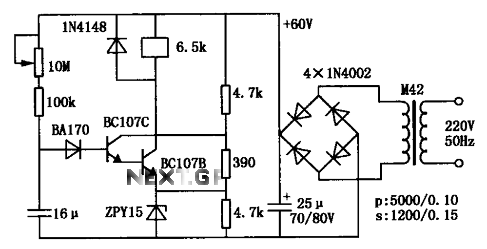
The circuit is a relay delay pull transistor configuration. Initially, when powered, the 16 µF capacitor has a voltage of zero, resulting in both transistors being off, and the relay remains inactive. As the 16 µF capacitor charges over...
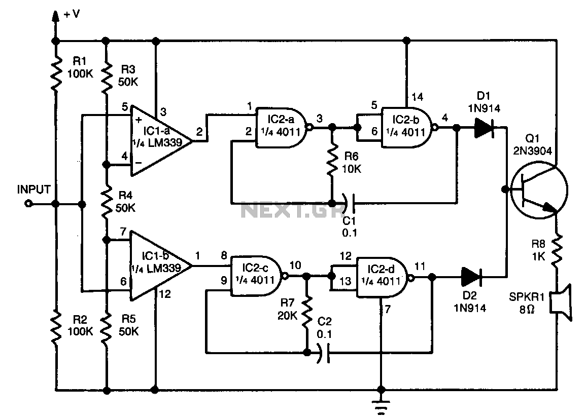
This tester provides an audible indication of the logic level of the signal presented to its input. A logic high is indicated by a high tone, a logic low is indicated by a low tone, and oscillation is indicated...
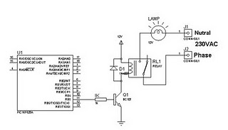
A relay can be controlled using a PIC microcontroller. The circuit illustrates how to control a single relay with the PIC 16F628. When the RB5 port of the PIC is set to high, the relay will activate. This circuit...