
Sawtooth Generator Circuit with 741 IC
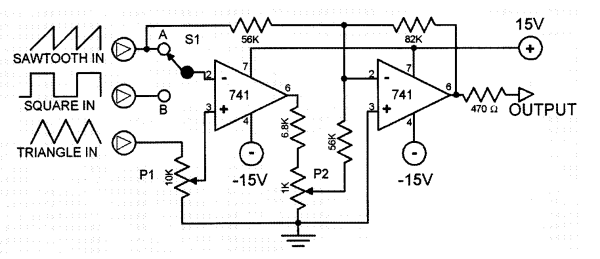
The sawtooth generator circuit primarily employs the 741 op-amp due to its versatility and availability. The configuration typically involves the op-amp in an integrator setup, where the output signal ramps up linearly and then quickly resets to produce the characteristic sawtooth waveform. The frequency of the sawtooth wave can be adjusted by varying the resistance and capacitance in the circuit, which is often accomplished using a variable resistor (P2).
In this circuit, the input signal is fed into the inverting terminal of the op-amp, while the feedback path includes a capacitor that charges and discharges based on the output voltage. As the capacitor charges, the output voltage rises, creating the linear ramp. Once the voltage reaches a predetermined threshold, the op-amp output switches states, causing the capacitor to discharge rapidly, resulting in the sharp drop characteristic of a sawtooth waveform.
The circuit may also include additional components such as diodes to protect against reverse polarity and resistors to set the gain of the op-amp. The output can be connected to a speaker or other audio processing equipment to produce sound. The frequency and amplitude of the output can be manipulated through the potentiometer and other passive components, allowing for a range of musical tones and effects to be synthesized. This makes the sawtooth generator a valuable tool in electronic music production and sound design.This sawtooth generator circuit use 741 IC and is used as a musical sound synthesizer. The sawtooth input signal is continously changed through P2 to a wav.. 🔗 External reference
Related Circuits
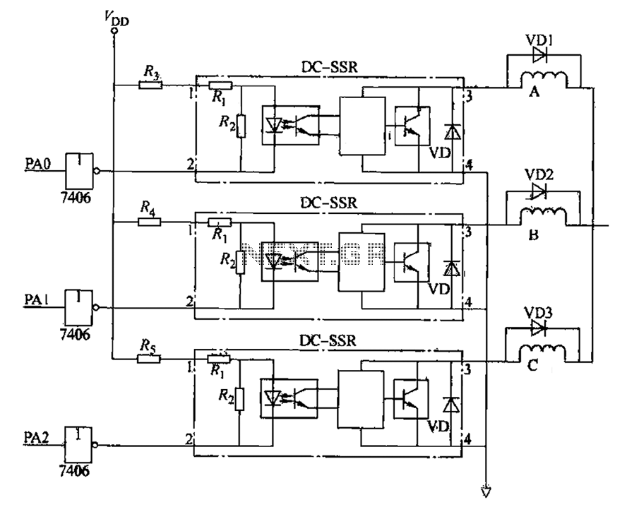
The figure illustrates that the DC Solid State Relay (SSR) in the input stage functions as an opto-isolator. When the switch output is high, the driver circuit inverts this signal to low. This process involves a light-emitting diode (LED)...
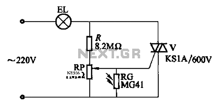
An automatic light control circuit is designed to illuminate a lamp when it is dark and to turn off the light at daybreak. The circuit, as shown in Figure 2-86, employs bidirectional thyristor tubes and features a straightforward design....
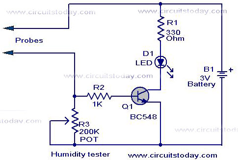
A simple humidity tester circuit using only an LED, a transistor, and a few resistors is explained with a clear circuit schematic. The humidity tester circuit is designed to provide a visual indication of humidity levels using basic electronic components....
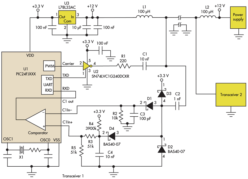
This circuit addresses the challenge of transmitting data over a cable that lacks available conductors. The data is modulated using On-Off Keying (OOK) and superimposed on a high-frequency carrier, allowing it to be transmitted over a low-voltage power supply...
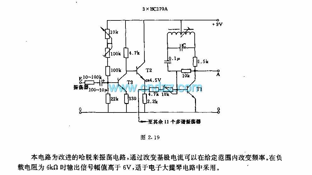
This circuit is an enhanced Hartley oscillator, which allows for frequency adjustment within a specified range by altering the base current. The output signal amplitude exceeds 6V when tested with a 6kΩ load resistance, making it suitable for use...

Frequency converter schematic, frequency to voltage converter schematic, frequency to voltage converter using TR, voltage to frequency converter application. A frequency converter is an essential electronic circuit that transforms frequency signals into corresponding voltage levels or vice versa. The frequency...