
First-order butterworth active Low-pass filter circuit
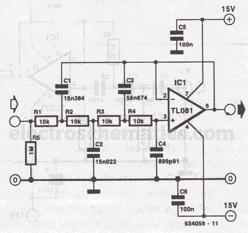
A Butterworth filter is designed to provide a maximally flat frequency response in the passband, ensuring minimal signal distortion. The filter's roll-off rate is moderate, providing a smooth transition between the passband and the stopband. The order of the Butterworth filter determines the steepness of the roll-off; higher-order filters exhibit a sharper transition but may introduce more phase distortion.
In practical applications, Butterworth filters are employed in various electronic circuits, including audio processing, communication systems, and signal conditioning. They can be realized using passive components such as resistors, capacitors, and inductors, or through active components like operational amplifiers. The most common configurations include low-pass, high-pass, band-pass, and band-stop filters.
The design of a Butterworth filter involves selecting the desired cutoff frequency and filter order based on the application requirements. The transfer function of an nth-order Butterworth filter can be expressed in terms of its poles, which are evenly spaced around a semicircle in the left half of the complex plane. This characteristic contributes to the filter's smooth frequency response.
When implementing a Butterworth filter in a circuit, careful consideration must be given to component tolerances and temperature stability to ensure the filter performs as intended across varying conditions. The filter's performance can be simulated using software tools to analyze its frequency response, phase response, and transient behavior before physical implementation.Butterworth filter is a filter whose freq response is flat over the passband region. British engineer Stephen Butterworth first described this 🔗 External reference
Related Circuits
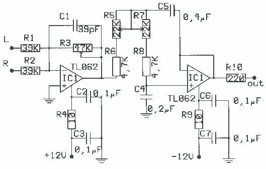
The application that we propose is a simple filter of region that limits the acoustic region (20-20000Hz) in the region 20-100Hz. With the manufacture that we propose, you can make an active filter in order to drive a loudspeaker...
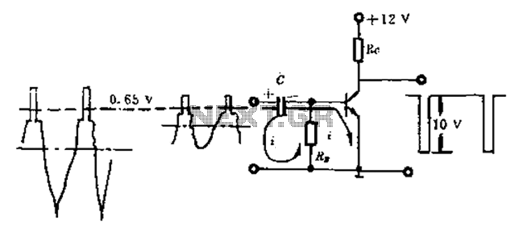
Amplitude separation circuit. A typical amplitude separating circuit is composed of a transistor, capacitance C, and resistances RB and RC. The input signal is a composite video signal, typically with a peak-to-peak voltage of about 2V. The output signal...
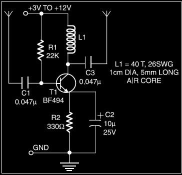
The circuit of an active shortwave antenna enhances weak shortwave signals, allowing for improved clarity when received by a shortwave receiver. The receiver does not need a physical connection; it can be placed within 6 to 7 cm of...
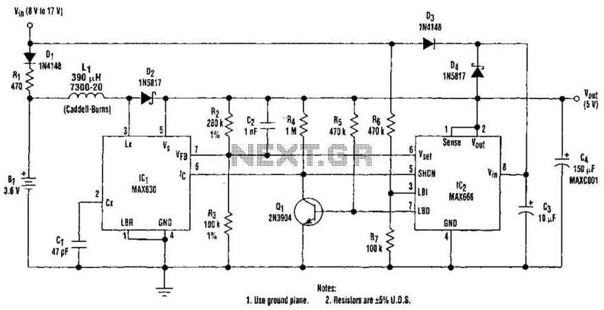
A 9-V wall adapter supplies Vm. IC2 contains a low-battery detector circuit that senses l7IN through resistors R6 and R7. The detector output at pin 7 drives an inverter (Q1), which in turn controls the shutdown inputs of IC1...
The yellow wires on the far right serve as temporary power connections, allowing battery power to enter through the contact studs located in the large holes that press against the radio's battery terminals. The cable in the lower right...
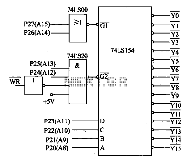
Decoding circuit: To ensure proper functionality of various interfaces, the system must assign IP addresses to all ports. Based on the number of system interfaces, it utilizes the 74LS154 decoder, which can translate up to 16 addresses. The interface...
Warning: include(partials/cookie-banner.php): Failed to open stream: Permission denied in /var/www/html/nextgr/view-circuit.php on line 713
Warning: include(): Failed opening 'partials/cookie-banner.php' for inclusion (include_path='.:/usr/share/php') in /var/www/html/nextgr/view-circuit.php on line 713