
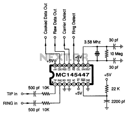
Audio Distortion Meter Circuit

The audio distortion meter is an essential tool in audio engineering, designed to quantify the level of distortion present in audio signals. Total Harmonic Distortion (THD) is a crucial parameter that indicates how much the output signal deviates from the original input signal due to non-linearities in the system.
The basic configuration of an audio distortion meter typically includes an input stage, a processing stage, and an output stage. The input stage usually consists of a buffer amplifier to isolate the audio source and prevent loading effects. This stage may also include a high-pass filter to remove any DC offset from the input signal, ensuring that only the AC components are analyzed.
The processing stage is where the actual measurement of THD occurs. This stage often employs a precision rectifier circuit to convert the AC signal into a DC signal, allowing for easier measurement of the distortion levels. A Fast Fourier Transform (FFT) processor may also be integrated to analyze the frequency components of the audio signal. By comparing the fundamental frequency with its harmonics, the processor can calculate the percentage of distortion present.
The output stage typically includes a display unit, which may be an analog meter or a digital readout, to present the distortion measurement to the user. Additionally, some designs may include a data logging feature, allowing for the recording of measurements over time for further analysis.
Overall, the audio distortion meter circuit diagram serves as a vital reference for engineers and technicians in the audio field, enabling them to ensure the fidelity and quality of audio systems by accurately measuring and diagnosing distortion levels.circuit diagram of audio distortion meter has been described here. Audio distortion meter is used to measure Total Harmonic Distortion. 🔗 External reference
Related Circuits
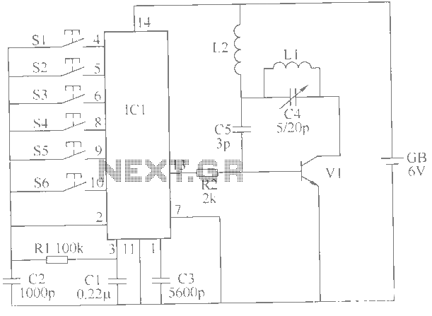
This example describes a wireless remote control switch featuring reliable operation and practical characteristics, capable of remotely controlling a 6-channel device within a 6-meter range for household electricity. The wireless remote control switch circuit consists of a wireless transmitter...
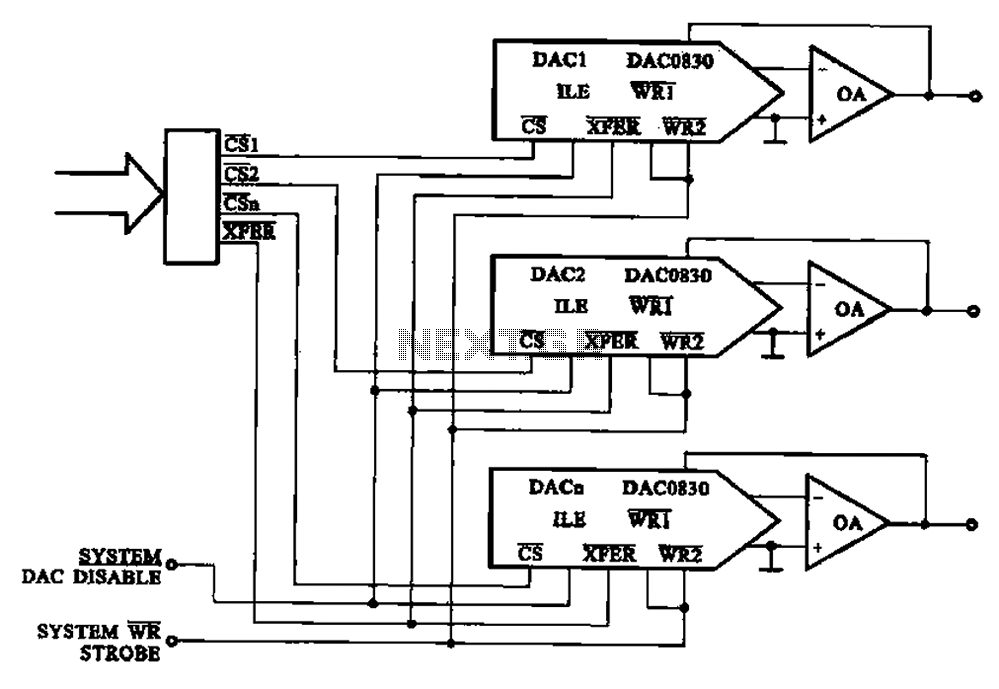
A multi-channel D/A converter circuit is presented, illustrating its fundamental structure. This circuit effectively converts encoded digital signals into multiplexed analog signal outputs. The multi-channel Digital-to-Analog (D/A) converter circuit is designed to facilitate the conversion of digital signals into corresponding...
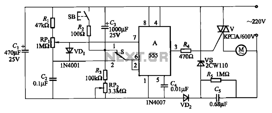
The circuit illustrated in Figure 3-12 incorporates variable speed and timing control functions. When switch S is set to position 1 and button SB is pressed, the motor initiates operation. After a predetermined delay, the motor automatically shuts down....
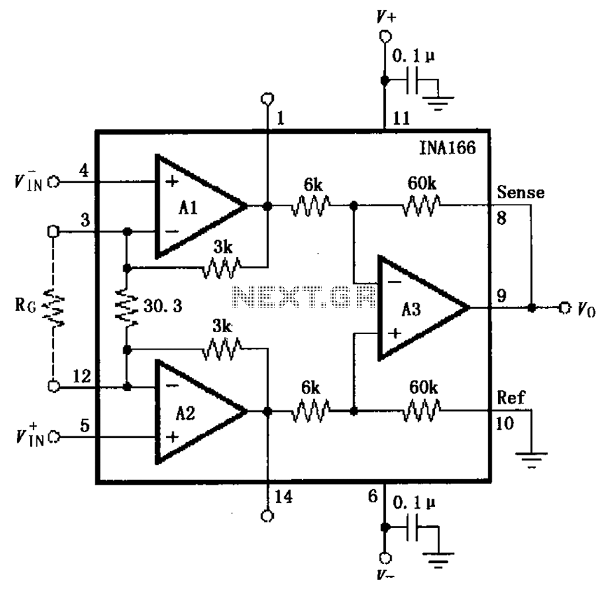
The basic connection circuit for the INA166 includes signal and power connections. A 0.1 µF tantalum capacitor should be used for filtering the chip's power supply terminal, and the PCB layout should be designed to position this capacitor as...
This circuit dials a stored DTMF tone sequence from an EPROM when a control line is taken to 0 V. IC1 is a Schmitt trigger oscillator, operating at approximately 2 Hz. It clocks a 4024 binary counter. The outputs...
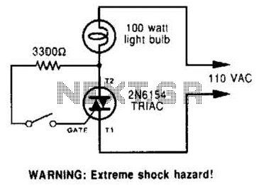
A triac can be utilized as a line-operated AC power switch that directly controls lamps, heaters, or motors. A brief current pulse into the gate activates the triac, and it remains on until the main current reverses. A triac, or...