
6m wireless remote control switch circuit
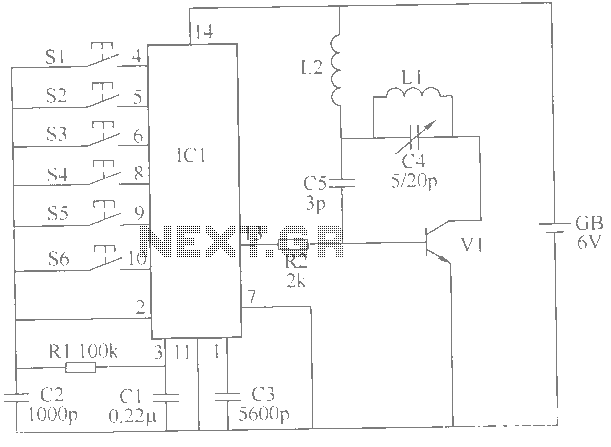
The wireless remote control switch is designed to facilitate the operation of multiple electrical devices from a distance, enhancing convenience and functionality in a household setting. The wireless transmitter section utilizes an integrated circuit (IC1) to encode signals from the control buttons (S1 to S6). Each button corresponds to a specific channel, allowing the user to selectively activate or deactivate connected devices.
The transmitter circuit includes a power supply unit, typically a battery (GB), which powers the entire system. Resistors (R1, R2) are employed for current limiting and voltage division, ensuring that the circuit operates within safe parameters. The inductors (L1, L2) may be used for filtering or tuning purposes, optimizing the signal transmission and reception.
The receiver circuit, which is not detailed in the initial description, is equally important as it decodes the signals sent from the transmitter. Upon receiving a signal, the receiver activates the corresponding output channel, which may be connected to a relay or a solid-state switch, allowing the control of high-voltage devices safely.
The operational range of 6 meters is typical for such wireless systems, achieved through careful selection of components and circuit design. The overall architecture of the wireless remote control switch circuit is compact and efficient, making it suitable for various applications around the home, such as controlling lights, fans, or other electrical appliances. The simplicity of the design ensures ease of use and installation, making it accessible for both amateur and professional electronics enthusiasts.This example describes a wireless remote control switch, with reliable operation, simple and practical features, can remote control 6-channel device in the 6m range of household electricity. The wireless remote control switch circuit by the wireless transmitter and wireless receiver circuit control circuit. Encoded by a wireless transmitter integrated circuit IC1, the control button S1 ~ S6, the transistor V1, resistors R1, R2, inductors L1, L2, and capacitors C1 ~ C5 battery GB, as shown in Fig.
Related Circuits
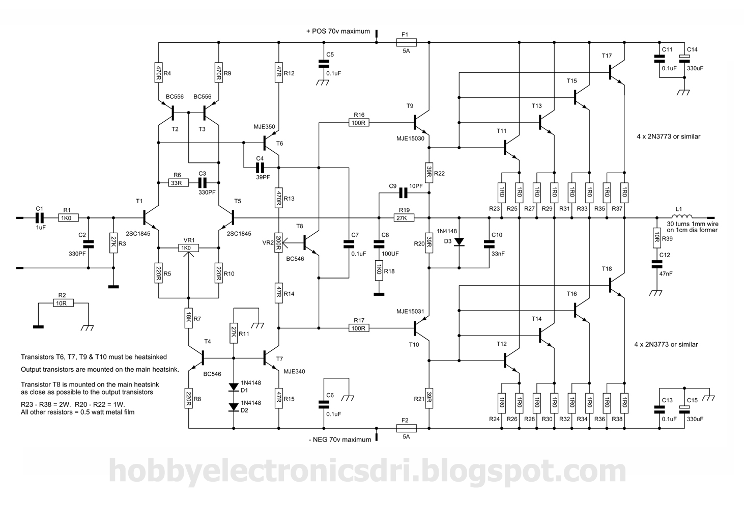
This amplifier was designed to utilize the otherwise unused TO3 power transistors that many hobbyists possess. With proper construction, the module can achieve high-quality performance and is rated for 300 watts into a 4-ohm load, depending on the power...
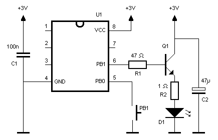
An infrared (IR) remote control designed for a Nikon DSLR camera. While not essential, it serves as an interesting project. The protocol used by the original Nikon remote controls ML-L1 and ML-L3 is straightforward, as explained by Big Mike...
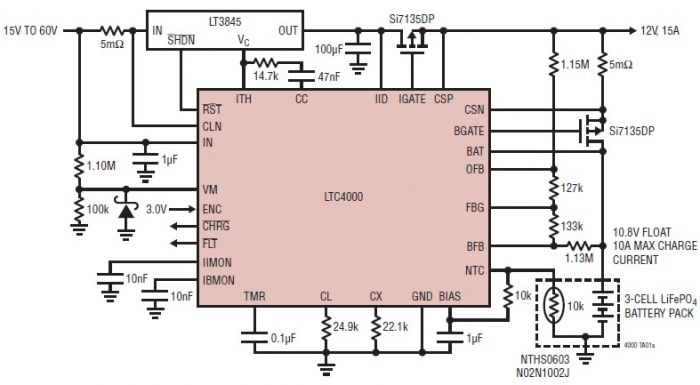
The LTC4000 high voltage controller, developed by Linear Technology, can be utilized to create a straightforward high current LiFePO4 battery charger. This charger delivers a fixed output voltage of 12 volts with a maximum output current of 15 A....
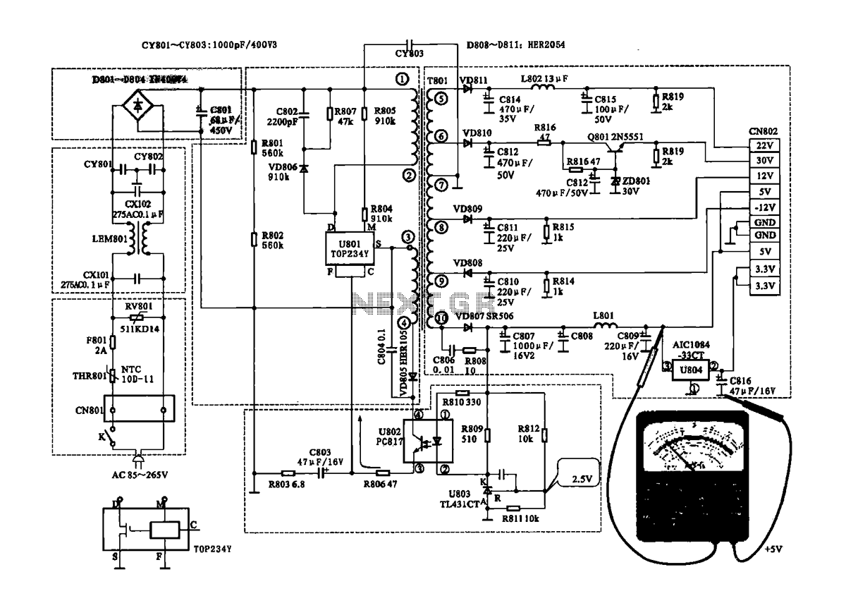
The Coship CDVB3188V receiver features a switching power supply circuit similar to the CDVB3188C model. The circuit includes several key components: an AC input circuit, an anti-jamming filter circuit, a complete flow filter circuit, and a switching oscillation circuit....
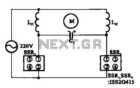
The triac motor drive circuit depicted demonstrates the operation of a TRIAC, which is often referred to as a solid-state relay. Figure (a) illustrates the circuit configuration, while figure (b) presents the connections for the motor coils. The triac motor...
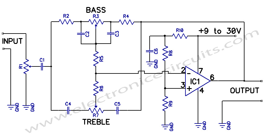
A preamplifier circuit featuring independent Bass and Treble tone controls is illustrated in this schematic. This circuit design utilizes operational amplifiers (op-amps) to achieve independent control over the bass and treble frequencies, allowing for enhanced audio customization. The preamplifier stage...