
Alarm Dialer Circuit

The described circuit operates on the principle of generating Dual-Tone Multi-Frequency (DTMF) signals using an EPROM and a binary counter. The core component, IC1, functions as a Schmitt trigger oscillator, which provides a stable square wave output at a frequency of approximately 2 Hz. This output is used to clock the 4024 binary counter, which counts in binary and thus produces a sequence of binary outputs corresponding to its count.
The outputs of the 4024 counter are connected to the address lines of the EPROM, specifically the 2716 model in this example. The 2716 EPROM is a 2K x 8 memory device, capable of storing a sequence of DTMF tones. The counter's output determines the address being accessed in the EPROM, effectively allowing the circuit to sequentially read the stored DTMF tone data.
In normal operation, the counter is held in a reset state by applying a logic high to its reset pin (pin 2). This prevents any counting from occurring until a trigger input is applied. When the control line is driven low, the circuit initiates its operation: pin 10 of IC1 transitions to a low state, which in turn causes pin 3 to go high, removing the reset condition from the counter. With the reset condition lifted, the counter begins to increment with each clock pulse from the Schmitt trigger oscillator, sequentially addressing the EPROM.
As the counter progresses through its counts, the EPROM outputs the corresponding DTMF tone data. The data on the least significant bit (D0) of the EPROM serves a critical role; when the address changes from 000000, D0 transitions to a logic high, which keeps the circuit operational. To ensure the circuit can return to a standby state, the last address accessed in the EPROM must contain the data pattern 11111110. This specific data instructs the circuit to reset, preparing it for the next operation cycle.
Overall, this circuit effectively demonstrates the use of a binary counter and an EPROM to generate and control a sequence of DTMF tones, showcasing a practical application of digital electronics in communication systems. This circuit dials a stored DTMF tone sequence from EPROM when a control line is taken to 0 V. ICl is a Schmitt trigger oscillator, running at around 2 Hz. It clocks a 4024 binary counter. The counter`s outputs connect to the address leads of the EPROM. A 2716 was used here, but the choice of EPROM is by no means critical. Normally, the counter is held reset by a logic 1 on its reset pin (pin 2). When the trigger input is sent low, pin 10 of ICl goes low, pin 3 goes high, and the reset is removed from the counter. It then begins to clock, incrementing the EPROM. When moved from address 000000, the data on bit DO of the EPROM changes to a logic 1 and holds the circuit running. The last address should have data 11111110 to reset the circuit to standby.
Related Circuits
A series of emails have been received requesting schematics for infrared remotes. This document presents a schematic for such a remote, which transmits a tone using an infrared LED. The tone is decoded by the receiver, ensuring that the...

This is a low-cost FM antenna booster designed to enhance reception of programs from distant FM stations. The FM antenna booster circuit features a common-emitter tuned RF preamplifier utilizing the VHF/UHF transistor 2SC2570 (C2570). The schematic illustrates the configuration...

This power supply is designed to power a 100-W low-frequency amplifier and is capable of supporting various mono or stereo amplifiers within the medium power range, specifically those that require 30 to 35 V. The power supply circuit is engineered...
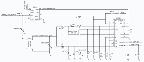
The UC3825 IC, manufactured by Texas Instruments, is a high-speed pulse width modulation (PWM) controller that serves as the central processor for a DC/DC converter control circuit. This circuit primarily consists of three integrated circuits: the UC3825BN, ISO124, and...

This light-sensitive circuit can operate a relay to switch on lamps or any AC loads when it detects darkness. It is ideal for use as a switchless night lamp. The circuit utilizes a light-dependent resistor (LDR) as its primary sensing element....
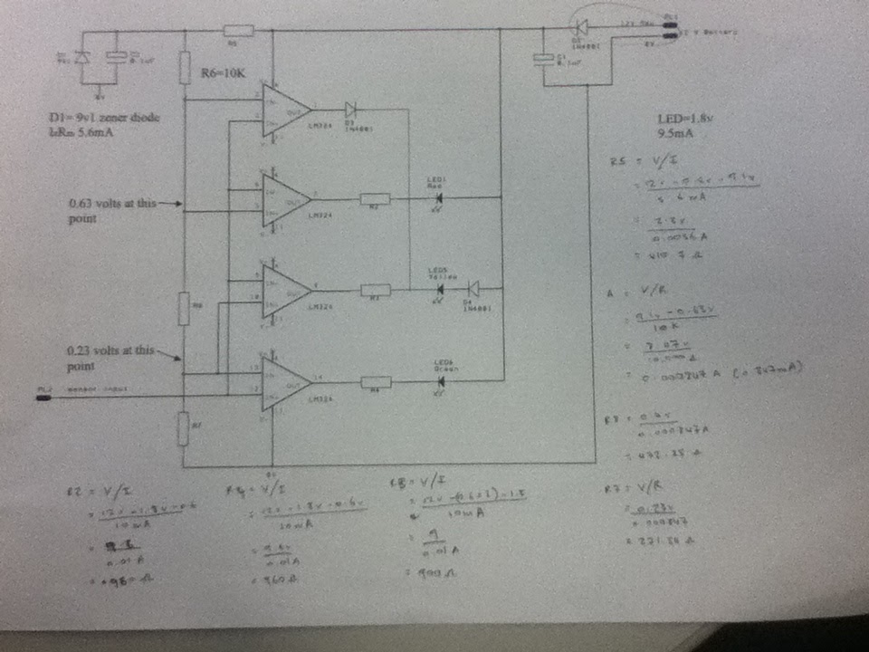
The diagram illustrates the connections for the inputs and outputs of each operational amplifier from the power source, detailing how each operational amplifier is configured to operate individual light-emitting diodes (LEDs). It also includes calculations for determining each resistor...