
Audio Electronics
The circuit schematic for the tunable notch filter is designed to facilitate harmonic distortion measurement in audio applications. It employs state-variable filter topology, which allows for precise tuning and adjustment of filter characteristics. The operational amplifiers, specifically the LF353, are configured to provide the necessary gain and filtering properties, with careful attention to power supply requirements to ensure optimal performance.
The inclusion of the MLT04 quad analog multiplier enhances the notch filter's functionality, enabling automatic tuning and nulling of the filter response. This feature is particularly beneficial when dealing with low distortion levels, as it simplifies the process of achieving accurate measurements.
The design considerations regarding the JFET input op-amps highlight the importance of understanding the operational characteristics of the components used, particularly in non-inverting configurations. The adjustments made to the circuit, including the shunting of resistors and the modification of component values, ensure that the filter operates within the desired parameters while minimizing distortion.
Furthermore, the addition of visual indicators such as the bi-color LED provides an intuitive interface for users, allowing for real-time feedback during the tuning process. The use of ten-turn potentiometers allows for fine adjustments, which are critical in achieving the desired performance from the notch filter.
Overall, the detailed schematic and accompanying descriptions provide a comprehensive guide for constructing and utilizing a tunable notch filter for audio applications, addressing common pitfalls and offering solutions for optimal performance.How to use a desktop computer to solve the complex arithmetic needed to design state-variable filters for audio use. Construction of a tunable notch filter for measuring harmonic distortion is featured. Audio Amateur Corp. did a beautiful job (as always)of editing and presenting my article. For those of you who are planning to build my notch filter however, several typos snuck in which should be clarified. Figure 5 on page 13 has both inputs on the left labeled as "Speaker Level Input". J1, the differential input, is correctly labeled, but J2, the single ended input, should have been labeled "Line Level Input". In the schematic diagrams, I didn`t show the power supply connections to the opamps, but probably should have.
Connect +15 Vdc (filtered, regulated, and bypassed) to pin 8 of each LF353. Connect -15 Vdc (filtered, regulated, and bypassed) to pin 4 of each LF353. On page 14 under the heading "Constructing the Prototype" I make a statement regarding the input preamp U4B that "distortion was higher when I configured the preamp for unity gain. " The increase in distortion is actually due to a design error on my part which is easily corrected. It turns out that JFET input opamps have a unique distortion mechanism that only comes into play when used in a non-inverting circuit, as is U4B in Figure 5.
Input capacitance varies with common mode voltage, making the inputs non-linear at high frequencies when the source impedance is high. This is the case for the inverting input of U4B when unity gain is selected. The solution is to configure SW3 so that R26 is shunted by a much smaller parallel resistance when unity gain is selected.
The following circuit diagram shows the correction: I learned about this issue from a Burr-Brown data sheet, available online at: OPA 134 Audio Operational Amplifier. I also changed the values of R25, R26, and C21 so that the amplifier gain is now exactly `times 10`. I`ve already finished one of the enhancements I mentioned on page 17 under the heading "Further Development".
I`ve used the MLT04 quad analog multiplier from Analog Devices to implement an auto-tune and auto-null add-on circuit. This makes the notch filter much easier to use, especially when measuring distortion levels of 0. 1% or less. Here is the complete schematic: Note that this circuit can be used without modifying the original notch filter circuit.
On my original prototype, I just added a jumper with connections for power, ground, x2, y(t), x1, and an input to the summation of b1, x2, and a1. I did however have to replace the power supply with a +/- 5 Vdc unit, since both the TLC2274 and the MLT04 must be used with +/- 5 Vdc supplies.
This had little effect on notch filter performance, but does limit headroom quite a bit. I follow the design of C. Lau [1980] pretty closely, although I used multipliers at U6A and U6B instead of choppers for synchronous detection. I`ve also added a bi-color LED to indicate if coarse tuning should be adjusted up or down. The front panel fine tune and null adjustments don`t affect operation of the automatic circuit, and can be left centered.
The 10-turn potentiometers are used to account for offset voltages in the multipliers and op-amps. With a 1 Vrms input having very low distortion, adjust the trim pots iteratively until notch filter output is minimized. Jog the front panel fine tune and null adjustments to watch the automatic adjustments take over. The auto tune and auto null circuits operate independently, and can be inhibited by shorting across either or both of the 33nF integrating capacitors.
🔗 External reference
Related Circuits
This simple circuit mixes two or more channels into one channel (eg. stereo into mono). The circuit can mix as many or as few channels as you like and consumes very little power. The mixer is shown with two...
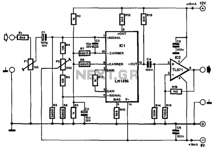
Often, the frequency of a signal must be doubled, and the modulator/demodulator chip LM1496 serves as an ideal basis for this application. From trigonometry, it is well known that 2sin(x)cos(x) = sin(2x) and sin^2(x) = 1 - cos^2(x). These...
Stationary - MOPLL & Silicon Tuner TUA6020 2 Band TV Tuner Mixer-Oscillator-PLL with balanced IF-Amplifier. The TUA6020 device integrates a digitally programmable Phase Locked Loop (PLL) with a mixer-oscillator block that includes two balanced mixers and oscillators suitable for...

This is a simple design of an audio level meter. The circuit utilizes a single integrated circuit (IC) and a minimal number of external components. It is based on the LM3915, which functions as the controller for the audio...
The simplest one-transistor audio mixer circuit diagram available. It utilizes a single transistor and can accommodate multiple audio signals, limited only by the user's budget. BC10. The one-transistor audio mixer circuit is a fundamental design that demonstrates the principles of...
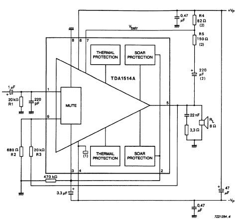
The TDA1514 audio amplifier circuit design is an electronic project capable of delivering high audio power output using a specialized audio integrated circuit (IC) and a few common components. Manufactured by Philips Semiconductor, the TDA1514 audio IC can provide...