
Audio-frequency generator circuit
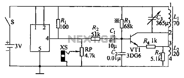
The audio frequency signal generator described operates within a specified frequency range, generating audio signals and modulated high-frequency signals. The circuit employs a high-frequency oscillator, which utilizes inductive (L) and capacitive (G) components to establish the desired oscillation frequency. The pilot signal from receptacle XS serves as a reference for generating various musical tones. The modulation of the high-frequency signal is accomplished through the interaction of resistor R and capacitor C1, which shape the output into amplitude-modulated waves.
The variable resistor RP plays a crucial role in controlling the output signal's amplitude, allowing for adjustments based on the application requirements. The magnetic antenna is designed with two windings, W1 and W2, which are critical for efficient signal transmission. W1, with 70 turns, and W2, with 20 turns, provide the necessary inductance for effective radiation of the high-frequency signal.
The tuning capacitor G is integral to the circuit's functionality, as it enables fine-tuning of the oscillation frequency. By adjusting capacitor C3, the operating frequency can be extended from 460 kHz to 1610 kHz, facilitating a wide range of applications. The design allows for flexibility in the number of turns in winding W1, accommodating different frequency requirements.
The bias resistor Yan is essential for stabilizing the transistor VT1, ensuring consistent performance. By maintaining the collector current within the specified range of 0.8 mA to 1.2 mA, the circuit achieves optimal operation and reliability. This comprehensive design allows for effective generation and modulation of audio and high-frequency signals, suitable for various electronic applications.An audio frequency signal generator shown in FIG. Can output audio signal, 465kHz spectral amplitude signals, 52,5Hz4-16Q5kHz high frequency amplitude modulated signal. VT1 hig h-frequency oscillator and the like, the vibration frequency of oscillation by the G, L. Decision. Manifold musical tone generated by the pilot signal on the one hand from the receptacle XS output, on the other hand by the R, c1 to modulate the high frequency signal to produce AM waves. Potential RP is used to adjust the size of the audio output signal., The high -frequency signal from the magnetic antenna direct radiation output by changing to adjust the distance and the relative position signal generator and a receiver the size of the output signal.
Magnetic antenna in the magnet forward Wl wound 70 turns, W2 around 20 turns. G is a tuning capacitor, change C3 should be able to cover 460kHz-1610kHz, or can increase or decrease the number of turns Wl achieved. Yan is the bias resistor, adjust Ningbo, make VT1 collector current of 0.8 ~ 1. 2mA can.
Related Circuits
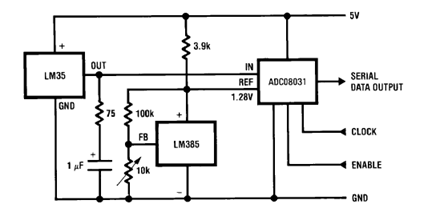
The circuit illustrates a Temperature to Digital Converter diagram utilizing the LM35 sensor, which includes a beneficial bypass capacitor connected from VIN to ground and a series RC damper. The described circuit employs the LM35 temperature sensor, a precision integrated...
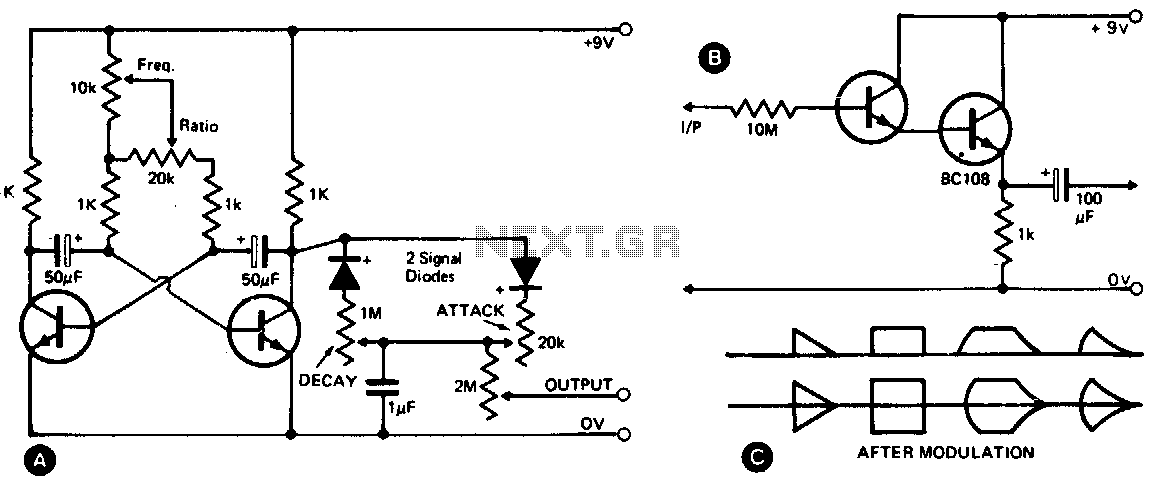
This waveshape generator functions as a slow-running oscillator with adjustable attack and decay times. It features a variable amplitude output, which is high impedance and can be controlled through a 2M potentiometer. Additionally, an add-on circuit is illustrated in...
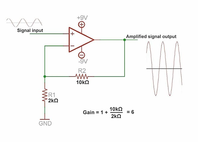
An amplifier is a device that increases the voltage in a circuit. The simplest type is an operational amplifier, and this video will demonstrate how these devices function and how to implement them in electronic applications. As an example,...
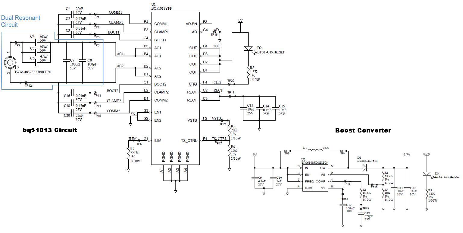
Several boards have been constructed using the bq51013 EVM receiver circuit along with a TPS61085 boost converter circuit, designed in SwitcherPRO Design Software, to elevate the voltage level to 5.7 volts. However, when a load of 580 mA, required...
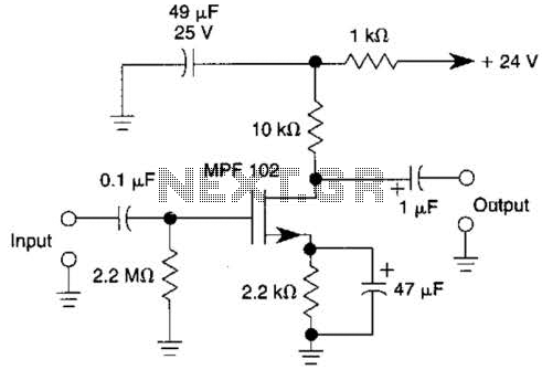
This JFET preamplifier has a gain of approximately 20 dB and a bandwidth exceeding 100 kHz. It is useful as a low-level audio amplifier for high-impedance sources. The described JFET (Junction Field Effect Transistor) preamplifier is designed to amplify low-level...
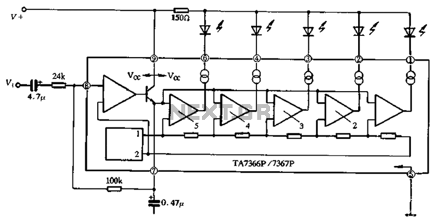
The TA 7366/7367 is a commonly used single display driver circuit manufactured by Toshiba Corporation. It features a 5 LED driver circuit and is designed in a 9-pin single in-line plastic structure. The circuit configuration includes an operational amplifier...