
Temperature to Digital ConverterCircuit using LM35
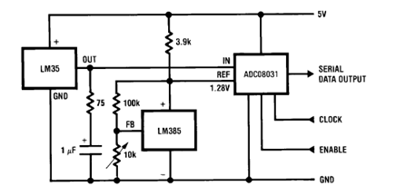
The described circuit employs the LM35 temperature sensor, a precision integrated circuit that outputs an analog voltage proportional to the temperature in degrees Celsius. The LM35 is known for its ease of use, as it does not require any external calibration and offers a linear output of 10 mV per degree Celsius.
In this configuration, the bypass capacitor serves a critical role in stabilizing the power supply voltage at the VIN pin of the LM35. By connecting the capacitor from VIN to ground, it filters out any high-frequency noise that may be present in the power supply line, thereby ensuring stable operation of the sensor. Proper bypassing is essential for accurate temperature readings, as fluctuations in supply voltage can lead to erroneous output signals.
The series RC damper included in the circuit is designed to mitigate any potential overshoot or ringing in the output signal. This is particularly important when interfacing the LM35 with an analog-to-digital converter (ADC), as rapid changes in temperature can produce transient spikes in the output voltage. The RC damper works by introducing a time constant that smooths out the response of the circuit, allowing for more stable and reliable readings.
Overall, the combination of the LM35 sensor, the bypass capacitor, and the series RC damper creates a robust temperature measurement system that can be effectively integrated into various electronic applications, such as environmental monitoring, HVAC systems, and temperature control mechanisms.Above circuit shows Temperature to Digital Converter diagram using this LM35 sensor with a useful bypass capacitor from VIN to ground and a series RC damper 🔗 External reference
Related Circuits
The circuit utilizes the CMOS 4017 decade counter integrated circuit (IC). Each press of a switch advances the output from 0 to 9. By connecting the output through an AND gate to the subsequent IC, a specific code must...
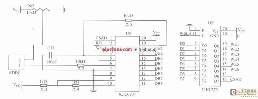
The circuit utilizes the ADC0804, which is configured for left-handed operation, alongside the 74HC573 latch, which is configured for right-handed operation. The latch is connected to a microcontroller, but they are not drawn in the same schematic. The CSAD...
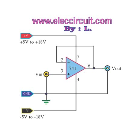
The buffer operational amplifier (op-amp) circuit is utilized for coupling two circuits together. It functions as a unity gain follower, also known as a voltage follower, which is employed to transfer or replicate a voltage from one circuit to...
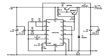
The schematic diagram below illustrates a 5V/1A Step-Down Switching Regulator utilizing the LM2524D Regulating Pulse Width Modulator (PWM). Additional parameters, PC board layout, stuffing diagram, and more information can be found in the LM2524D datasheet. The circuit design features the...
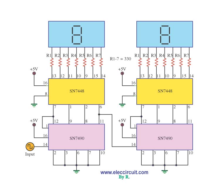
A decade counter circuit is an electronic circuit designed to perform a sequence of numerical calculations, allowing for either forward or backward counting. Forward counting refers to the circuit counting from smaller to larger numbers, while backward counting is...
The character data and command from the microcontroller is transferred serially to a shift register (74HC595), and the parallel output from the shift register is fed to LCD pins. 74HC595 is a high-speed 8-bit serial in, serial or parallel-out...