
Audio Level Meter
The audio level meter circuit is designed for precise monitoring of audio signals across a wide frequency range, making it suitable for various applications in audio engineering and sound system diagnostics. The use of discrete components allows for flexibility in design and adaptability to specific requirements.
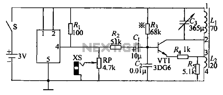
The first stage of the circuit, utilizing a common emitter amplifier configuration, serves to amplify the incoming audio signal. The presence of a preset resistor in this stage enables fine-tuning of the gain, allowing the user to set the meter's sensitivity to the desired level. This adjustment is crucial for achieving accurate readings, especially in environments where audio levels may fluctuate significantly.
The second common emitter amplifier stage further amplifies the signal while ensuring that the output is biased to operate at approximately half the supply voltage. This biasing technique is essential for maximizing the AC voltage swing, thereby allowing the meter to respond effectively to the variations in audio signal levels without distortion.
The inclusion of a 10µF DC blocking capacitor is vital for preventing DC offset from affecting the measurement. This capacitor allows only the AC components of the audio signal to pass through, ensuring that the rectification process accurately reflects the amplitude of the audio signal. The full-wave bridge rectifier then converts this AC signal into a varying DC voltage, which can be easily read by the panel meter.
Overall, this audio level meter circuit is a robust solution for monitoring audio levels with high fidelity and precision, making it an invaluable tool for audio professionals and enthusiasts alike.This is audio meter that can be monitored using a small panel meter with this circuit built from discrete components. The audio level meter circuit has a flat frequency response from about 20Hz to well over 50Khz. Input sensitivity is 100mV for a full scale deflection on a 100uA meter. Built on two common emitter amplifiers, the first stage has a preset resistor which may be adjusted for a FSD. The last stage is biased to operate at roughly half the supply voltage for maximum ac voltage swing. Audio frequencies are passed through the 10u dc blocking capacitor and the full wave bridge rectifier converts the signal to a varying dc voltage. 🔗 External reference
Related Circuits
The problem with class-B amplifier design is that we start with an output stage in two halves, each with a non-linear response, which we then add together to try to give a linear response, i.e. so that a graph...
An audio frequency signal generator can output audio signals, 465 kHz spectral amplitude signals, and 52.5 Hz to 16 kHz high-frequency amplitude-modulated signals. The high-frequency oscillator's vibration frequency is determined by the components G and L. A variety of...
The design presented here works by applying a 50kHz, 200mV square wave to the capacitor under test, in series with a 10 Ohm resistor. The AC voltage appearing across that resistor is measured and displayed on a meter. So...
Electromagnetic flow meter: How to measure fluid flow using a magnetic field. An electromagnetic flow meter is a device used to measure the flow rate of conductive fluids by utilizing Faraday's law of electromagnetic induction. This principle states that when...
This circuit combines two or more audio channels into a single channel (for example, mixing stereo into mono). The design allows for the addition of multiple channels, consuming minimal power. Although the schematic illustrates two inputs, it is possible...
Read the generic sound level from an electret microphone. Several schematics utilize NPN transistors that yield an inverted output (~5V when quiet, ~0V when loud, with linear operation in between). However, a non-inverted output is desired, where a super...