
Audio line driver

The two-channel audio line driver circuit employs the TSH22 dual op-amp IC, which is renowned for its high performance in audio applications. The op-amps are configured as non-inverting amplifiers, allowing for a gain of 3, which is suitable for boosting audio signals without introducing significant distortion. The configuration ensures that both channels maintain a balanced output, essential for stereo applications.
In this design, the non-inverting inputs of the op-amps are connected to audio input lines, facilitating the amplification of audio signals. The resistors R1 and R9 serve as biasing elements, providing a stable reference voltage to the non-inverting inputs, which is crucial for maintaining linearity and preventing signal clipping during high modulation levels.
Additionally, the phantom ground created by resistors R4 and R2 at half the supply voltage is a vital aspect of the circuit. This setup allows the op-amps to operate effectively within their linear range and ensures that the output signals are centered around a reference point, minimizing noise and improving overall audio quality.
Overall, this circuit design exemplifies a robust approach to audio signal amplification, utilizing high-performance components and careful biasing techniques to achieve optimal performance in two-channel audio applications.This is the circuit diagram of a two channel audio line driver using the high performance dual opamp IC TSH22 from ST Microelectronics. The 25 MHz bandwidth, low distortion and high output current of the IC makes it possible to drive medium impedance loads at a high level of modulation.
Here both of the opamps inside the IC are wired as non invert ing amplifiers with 3X gain, one for each channel. Input line 1 is connected to the non inverting input of IC1a and input line 2 is connected to the non inverting input of IC1b. The non inverting inputs of the opamps IC1a and IC1b are pulled to a slight positive voltage using the R1 and R9 respectively.
The resistance R4 and R2 are used to make a phantom ground at half the supply voltage. 🔗 External reference
Related Circuits
At low output power, up to 18 W, the device functions as a standard BTL amplifier. When a greater output voltage swing is necessary, the internal supply voltage is increased using external electrolytic capacitors. This momentarily elevated supply voltage...
This application note outlines the transmission of I²S audio data streams between two audio components using a single shielded twisted-pair (STP) wire, employing the MAX9205 10-bit LVDS serializer and the MAX9206 10-bit LVDS deserializer. Low-voltage differential signaling (LVDS) serves...
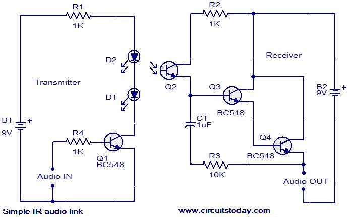
This circuit features a simple infrared (IR) audio link designed to transmit audio signals over a distance of up to 4 meters. The audio signal to be transmitted is applied to the base of transistor Q1 through resistor R4....
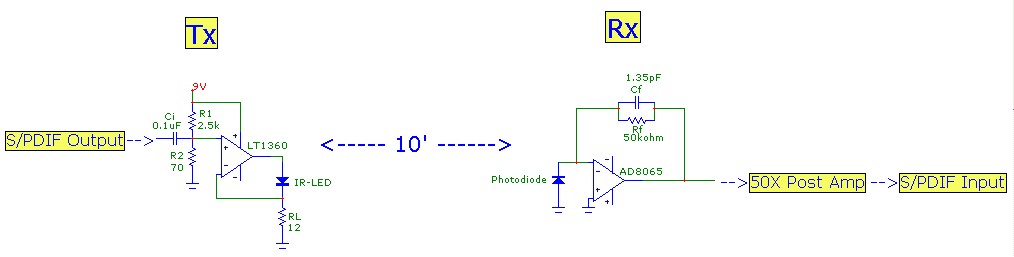
This article aims to illustrate a basic optical LED wireless link for transmitting high-definition (HD) S/PDIF digital audio streams. Circuit designs for both the transmitter (optical modulator) and receiver are provided, utilizing cost-effective op-amp configurations. Specific components are listed,...
Various techniques demonstrate how enhanced PWM (pulse-width modulation) intensity control can be utilized in LED (light-emitting diode) drivers. PWM intensity control is a widely adopted method in LED driver circuits to regulate brightness levels. This technique involves modulating the width...
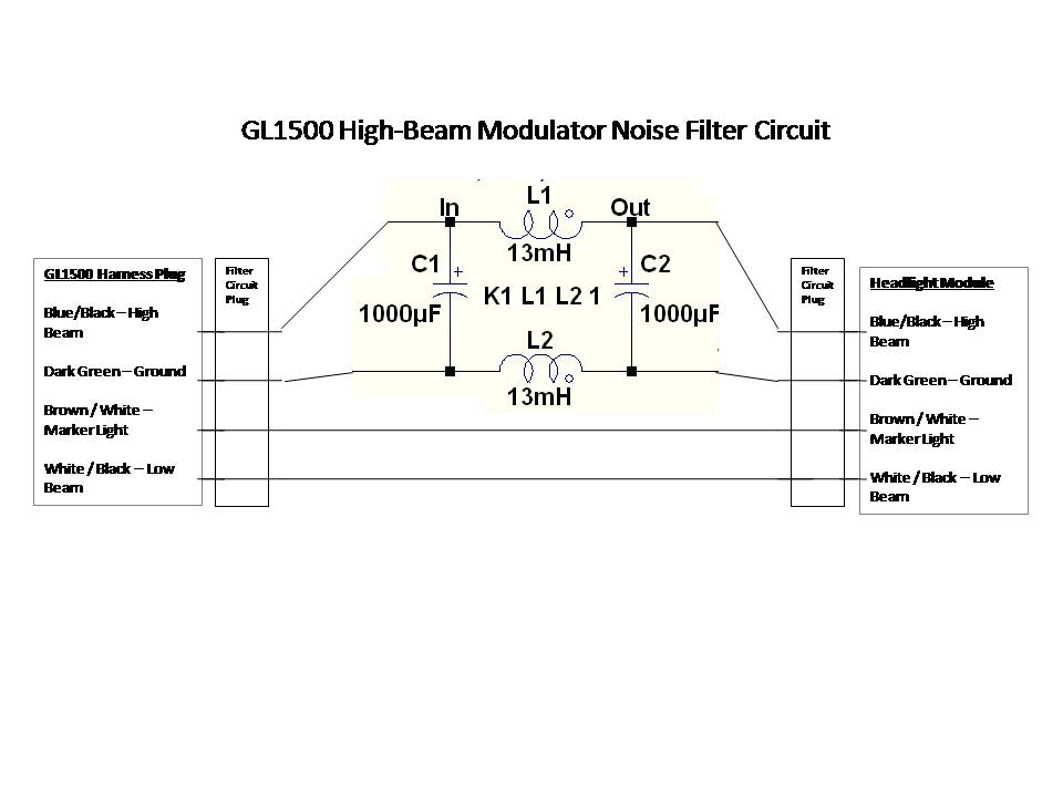
A power filter is a device that is placed before devices such as GPS, MP3 players, or radar detectors connected to the auxiliary circuit. When properly used and installed, these filters can eliminate modulator noise from any system. Observing...