
Simple IR audio link

The circuit operates by converting audio signals into infrared light pulses, which are then transmitted wirelessly. The modulation of the audio signal onto the IR light is accomplished through the switching action of Q1, which controls the intensity of the IR LEDs based on the input audio levels. The choice of R4 is critical, as it sets the base current for Q1, directly influencing the modulation depth and the efficiency of the transmission.
Upon reception, phototransistor Q2 detects the modulated IR signals. The output voltage from Q2 varies with the intensity of the incoming IR light, which corresponds to the audio signal's amplitude. This voltage change is then amplified by transistors Q3 and Q4, which are configured in a common-emitter arrangement to provide sufficient gain for driving output devices like speakers or headphones.
C1 and R3 serve a dual purpose in the circuit. C1 acts as a coupling capacitor, blocking any DC component and allowing only the AC audio signal to pass through to the amplifier stage. R3, in conjunction with C1, forms a low-pass filter that helps to smooth out any high-frequency noise that may be present, ensuring a cleaner audio output.
Overall, this IR audio link circuit is a practical solution for wireless audio transmission, effectively utilizing basic electronic components to achieve reliable performance over a short range. Proper component selection and configuration are essential for optimal functionality and signal integrity.Here is a simple IR audio link that can be used to transmit audio signals up to 4 meters. The signal to be transmitted is applied to the base of Q1 via resistor R4. The transistor Q1 drives the IR transmitting diodes D1 and D2. The audio input will be modulated to the IR signals transmitted. The transmitted IR signals will be picked by the photo tra nsistor Q2. The emitter voltage of the transistor Q2 will change according to the sound modulated to the IR signal. The transistors Q3 and Q4 amplifies this signal to drive the speaker or headphone. C1 and R3 forms a filter to avoid interference from stray IR signals. 🔗 External reference
Related Circuits
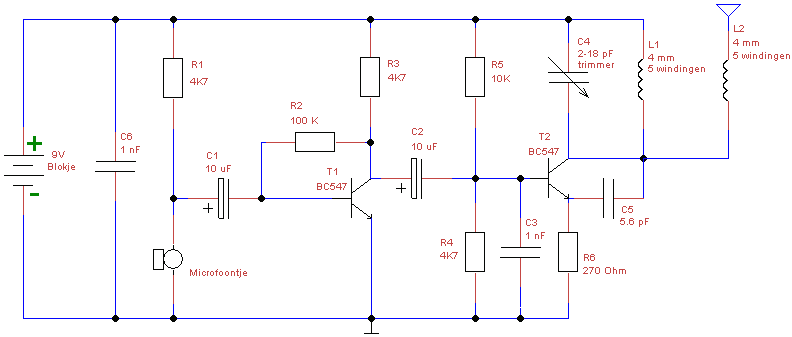
This is a simple design of a small FM transmitter bug that is ideal for transmitting and eavesdropping purposes. Due to its high sensitivity, it can even pick up the ticking of a clock. The estimated range is approximately...
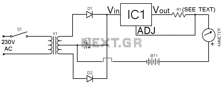
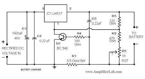
This Ni-Cd battery charger is a circuit utilizing the LM317 regulator IC. The design is straightforward and requires minimal components. By adjusting the value of resistor R1 between 1 ohm and 120 ohms, the charging current can be modified...
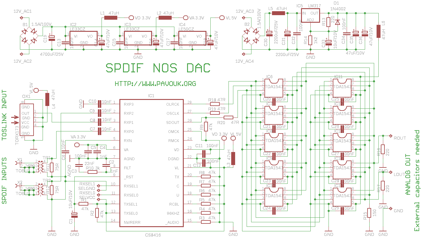
This circuit is an experiment designed to build a high-quality digital-to-analog converter (DAC) with optical input (TOSLINK), electrical input (S/PDIF), and USB input. Both electrical inputs are galvanically isolated from the DAC. The circuit is intended as part of...
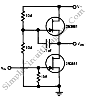
This is a simple high-gain JFET audio amplifier circuit. This circuit requires very low power but provides a high-gain amplification function. It is also referred to as JFET. The JFET (Junction Field Effect Transistor) audio amplifier circuit is designed to...
This document outlines a simple PWM (Pulse Width Modulation) DC to AC voltage inverter circuit based on the SG3524 integrated circuit. The SG3524 is a fixed frequency PWM voltage regulator control circuit that offers indifferent outputs suitable for both...
The circuit diagram of a lead-acid battery charger is presented here. The main component of this circuit is the IC LM317. The lead-acid battery charger circuit utilizing the LM317 voltage regulator is designed to efficiently charge lead-acid batteries while providing...