
Transmitting Audio Streams in Automotive Applications Using the MAX9205/MAX9206 LVDS SerDes

The MAX9205 and MAX9206 integrated circuits facilitate the efficient serialization and deserialization of I²S audio data streams. The MAX9205 serializer converts parallel I²S audio signals into a serialized LVDS format suitable for transmission over a single STP wire. The MAX9206 deserializer then converts the LVDS signal back into parallel I²S audio signals at the receiving end. This two-way communication method allows for the transfer of multiple audio channels while maintaining signal integrity and minimizing the risk of data loss due to interference.
The design emphasizes the importance of maintaining a DC-balanced signal to ensure reliable transmission. The approach of using the remaining inputs of the MAX9205 to achieve DC-balance by inverting certain data signals is a practical solution to meet this requirement. The careful consideration of the sampling timing, particularly ensuring that signals are stable during sampling, is critical for preventing jitter and ensuring high-quality audio output.
Additionally, the use of shielded twisted-pair wiring enhances the robustness of the transmission by reducing electromagnetic interference, which is particularly beneficial in automotive environments where various electronic systems operate simultaneously. The overall architecture allows for a simplified integration into existing systems, leveraging the advantages of LVDS technology to provide an efficient and effective means of transmitting high-fidelity audio data within vehicles.This application note describes how to transmit I ²S audio data streams between two audio components across a single, shielded twisted-pair (STP) wire using the MAX9205 10-bit LVDS serializer and the MAX9206 10-bit LVDS deserializer. Low-voltage differential signaling ”the most effective interface for in-vehicle digital video routing ”c
an also be used as a low-cost solution to transmit digital audio data streams. This application note details how to use the MAX9205 / MAX9206 10-bit LVDS serializer/deserializer ( SerDes ) ICs for transmitting up to four I ²S audio data streams across STP wiring. Refer to the MAX9205/MAX9206 data sheets for detailed information on these ICs. Since each time an audio signal is converted between analog and digital domains the sound quality is degraded, it is important to keep audio data in digital form when possible in order to provide the best sound quality.
The MOST ® bus is designed for in-vehicle audio data transmission but is expensive to implement and overkill for most applications. For consumer audio equipment, S/PDIF is commonly used to transmit compressed audio data from one piece of audio equipment to another.
However, S/PDIF does not have the bandwidth to transmit 5. 1 or 7. 1 digital audio in an uncompressed format and lacks a proven, robust physical layer for automotive applications. Transmitting digital audio data using LVDS provides a robust, low-cost, high-bandwidth interface solution that can be easily added to existing hardware without impacting system resources.
Digital audio data in the form of I ²S streams, which are already available, can be transmitted to a different location in a vehicle with virtually no software overhead. By keeping the audio data in digital form, multiple ADCs, DACs, and wires can be eliminated from the system, thereby freeing up cost and board space for other features.
LVDS is already used to route video data from cameras, DVD players, and navigation systems to various displays in the vehicle. Its low signal amplitude and differential structure allow LVDS to transmit high-bandwidth data with low electromagnetic radiation.
The MAX9205 is designed to transmit 10-bit parallel data from a single reference clock. To transmit the I ²S signals SCLK, WS, and SDA0 3 as data, we need a reference clock that is synchronous to SCLK and at least two times the frequency. Signals that leave a module in the wiring harness must be robust to withstand the harsh automotive environment and failure conditions.
The LVDS bus needs to be AC-coupled to prevent damage if high-voltage short conditions occur. Since the MAX9205 does not automatically DC-balance the outgoing signal we must make sure that the data being transmitted is in fact DC-balanced. Since we are using no more than six of the ten available inputs we can use the remaining four inputs to DC-balance the transmitted data.
The SCLK and WS signals are symmetrical signals so we only need to invert the random signals SDA0 3 and feed them into the unused inputs to ensure that the number of ones and zeros are equal for every 2-channel I ²S packet transmitted. To meet the setup and hold times for the MAX9205 and prevent excess jitter at the output of the MAX9206 deserializer, the I ²S signals should be sampled when they are not changing state.
Connect TCLK_R/F to GND to enable the MAX9205 to sample the inputs on the falling edge of the reference clock (TCLK). This assumes that the rising edge of TCLK corresponds to when SCLK changes state. If this is different than your configuration, make the appropriate adjustment to TCLK_R/F to ensure that the setup and hold times for the inputs are met.
See Figure 1 below for the proper sampling of the I ²S input signals. The left side of the schematic (labeled "Serializer") contains the circuit needed to serialize and transmit the LVDS audio data streams. Table 1 contains a list of components and signal descriptio 🔗 External reference
Related Circuits

The circuit below demonstrates the generation of a single positive pulse that is delayed in relation to the trigger input time. It is similar to a previously described circuit but utilizes two stages, allowing for control over both the...
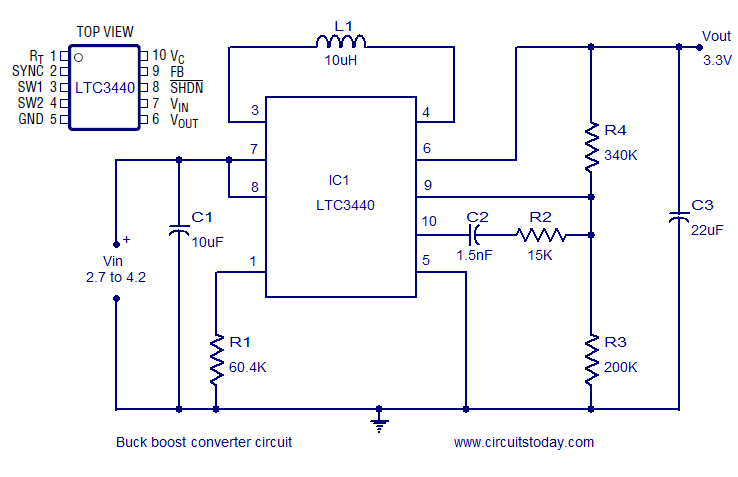
A simple and highly efficient buck-boost converter is implemented using the LTC3440 integrated circuit. The output voltage is set at 3.3V, while the input voltage range can vary from 2.7V to 4.2V. The LTC3440 is a synchronous buck-boost converter designed...
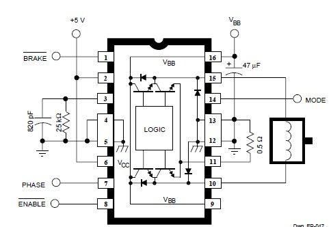
The main features of the MULTIWATT Package, a trademark of SGS-THOMSON Microelectronics, include a power amplifier IC designed specifically for car radio applications. It offers a high current capability of 3.5A and can drive a very low impedance of...
This simple DC servo motor circuit design can be utilized in various electronic projects. The circuit schematic illustrates that this DC servo motor driver employs a single integrated circuit along with a few external electronic components. For bidirectional DC...
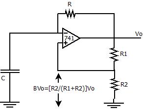
The positive feedback comparator circuit enhances the gain of the operational amplifier (op-amp), facilitating rapid switching between the two states of a multivibrator. This positive feedback also introduces hysteresis into the circuit. A capacitor, denoted as `C`, is connected...
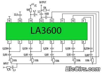
Circuit LA3600 5 Band Equalizer Circuit Schematics. One type of tone control in audio electronics is the graphic equalizer. Graphic equalizers can be categorized into two types: bar and other configurations. The LA3600 circuit is a 5-band graphic equalizer designed...