
circuit power audio amplifier with

The 2.1 amplifier circuit described is an effective solution for enhancing audio systems, particularly in environments where quality sound output is a priority. The design incorporates a symmetric power supply, ensuring stable voltage and current delivery to the amplifier stages. The use of a transformer with dual secondary outputs allows for straightforward integration into various power systems, while the inclusion of a fuse and switch adds a layer of safety and convenience for users.
The bridge rectifier, GBU606, is crucial for converting the AC voltage from the transformer into DC voltage, which is necessary for the operation of the amplifier. The filtering capacitors (C1, C2, C3, and C4) smooth out the rectified voltage, providing a steady DC supply to the amplifier circuits. The choice of electrolytic capacitors with a minimum value of 4700 µF ensures that the power supply can handle dynamic audio signals without significant voltage drops.
The operational amplifiers (7812 and 7912) provide regulated power supply voltages for the high-pass filter, which is essential for maintaining audio clarity, particularly in the treble range. The dual potentiometer allows for synchronized volume control of both satellite channels, simplifying user interaction.
The feedback network formed by resistors R7 and R9 is vital for setting the gain of the amplifier, allowing for customization based on the specific application or user preference. The compensation network (R20 and C23) is designed to optimize speaker performance, ensuring that the audio output remains clear and undistorted across various frequencies.
The subwoofer integration through operational amplifier IC4A NE5532 enhances low-frequency response, significantly improving the overall audio experience. The low-pass filter composed of C9, C10, and R10 effectively isolates the bass frequencies, ensuring that the subwoofer delivers deep, rich sound without interference from higher frequencies.
Overall, this 2.1 amplifier circuit exemplifies a well-thought-out design that balances performance, usability, and safety, making it suitable for a wide range of audio applications.This circuit is a complete application is 2. 1 amp, two satellite speakers for TDA and one for the subwoofer, making the 2. 1 system, widely used in commercial applications as an amplifier for computers, which may give an increased in its audio system with a stereo amplifier + bass amplifier (subwoofer). The power supply is of symmetric type, using a transformer, 110 or 220 with dual secondary 12 volts and 3A current. I recommend using a fuse and a switch before the transformer. B1 is a bridge rectifier least 100 volts / 4 A, an example that can be used is GBU606, the filtering circuit is formed of the capacitors C1, C2, C3 and C4, the electrolytes can have values from 4700 F. The power supply for the op amp Highpass filter, is used three terminal integrated circuits 7812 and 7912.
The left and right channels give exactly the same, let`s see how the left channel: LIN is the audio input jack, which is coupled by C20 to the pot volume adjustment, it is a double pot, and set the two channels simultaneously. R19/C22, helps to improve the signal of the treble. The capacitor C21 couples the signal to CI6 TDA2030, after amplified audio output is pin 4 of integrated.
The resistor R7 and R9 are responsible for feedback, so by changing the value of R7 can increase or decrease the gain of the amplifier. R20 and C23 form the compensation network for the speakers. The signal comes from the subwoofer to the left and right channels by resistors R15 and R10 being decoupled by capacitor C12, is applied in the operational amplifier 1 IC4A NE5532, which forms a pre-amplifier to boost the signal by 6 times.
Determined by R6/R8 resistor. The components C9, C10 and R10 form a low pass filter in this case is calculated to 200Hz. After leaving IC4B the low frequency audio through the potentiometer P1 that makes the volume level, then forwarded to IC3 is what makes the subwoofer amplifier, the operating principle is the same as satellite amplifiers. 🔗 External reference
Related Circuits
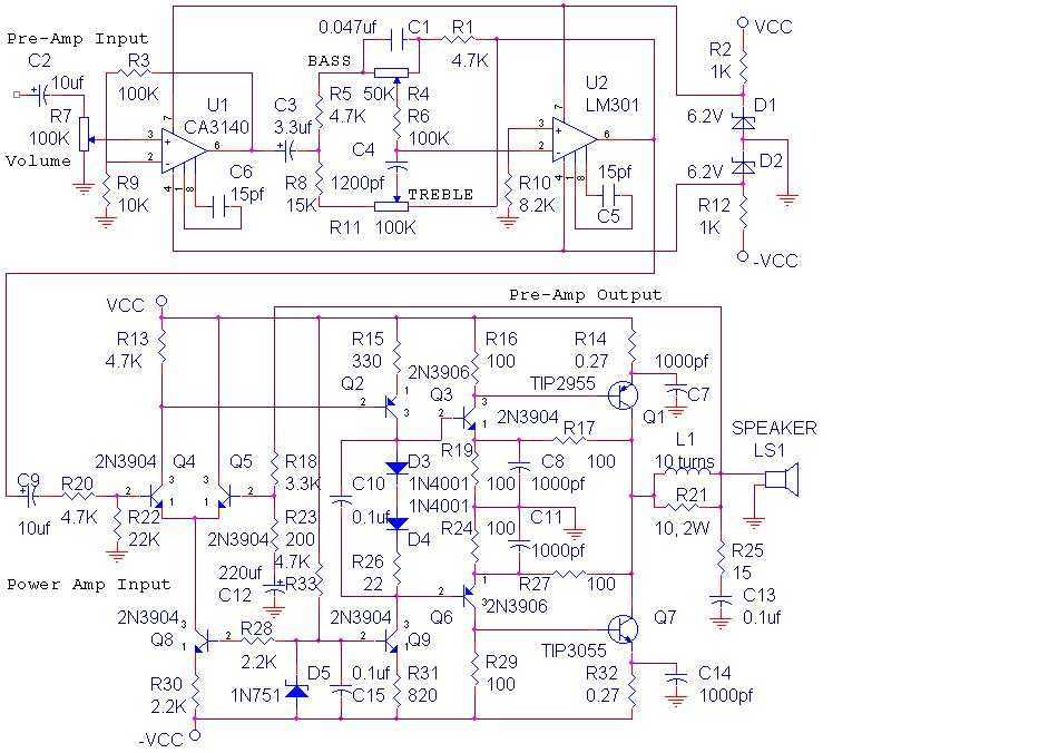
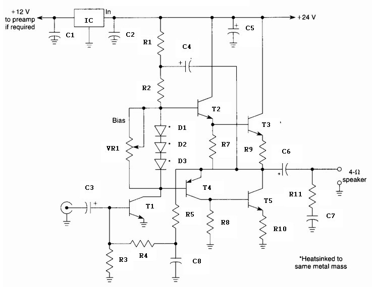
The audio amplifier shown below provides 14 watts of power, but can provide much more simply by increasing the power supply voltage. This amp was built in 1975 and has worked reliably ever since. The power amp portion was...
The circuit presented is a straightforward yet efficient amplifier that can provide notable performance enhancements. This amplifier can demonstrate negative resistance at lower settings of the 500-ohm potentiometer, resulting in increased gain or even oscillation. Consequently, the circuit can...
A Variable DC Power Supply is one of the most useful tools on the electronics hobbyist's workbench. This circuit is not an absolute novelty, but it is simple, reliable, robust, and short-proof, featuring variable voltage up to 24V and...
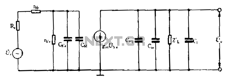
Common emitter amplifier circuit with resistance and capacitance coupling. The common emitter amplifier circuit is a fundamental configuration in analog electronics, widely utilized for its ability to amplify voltage signals. This circuit employs a bipolar junction transistor (BJT) as the...
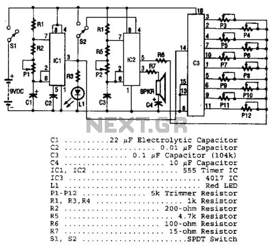
Three integrated circuits (ICs) are utilized to generate sounds. IC1 is a 555 timer configured as an astable multivibrator, producing clock pulses. The frequency of these clock pulses is adjustable via a trimmer potentiometer, P1. These clock pulses are...
A 10 Watt audio amplifier circuit diagram is presented. This circuit serves as a general-purpose 10-W power audio amplifier, suitable for medium power applications or for use in modulation within AM transmitters. To achieve higher power levels, up to...