
Audio Mixer Circuit

The mixer circuit utilizes the LM3900 quad operational amplifier, which is well-suited for audio applications due to its low noise characteristics and high input impedance. The circuit architecture integrates two line-level inputs and two microphone-level inputs, enabling the simultaneous processing of different audio sources.
At the input stage, each line and microphone input is connected to the non-inverting terminals of the op-amps within the LM3900. The gain of the op-amp can be adjusted using resistors R7 through R10, which form a feedback network around each op-amp. By changing the values of these resistors, the overall gain of the mixer can be modified, allowing for a maximum gain of approximately +23 dB.
The output of the op-amps is then summed together, providing a mixed audio signal at the output terminal. This output can be further processed or amplified as required. The design ensures that the mixer maintains a balanced audio signal, minimizing distortion and preserving the integrity of the original sound sources.
Overall, this mixer circuit is versatile and can be utilized in various audio applications, including live sound reinforcement, recording studios, and broadcasting, where multiple audio inputs need to be combined effectively. Designed around an LM3900 quad op amp, this mixer combines 2-line and 2-mike inputs and sums them at the output terminal. R7 through RIO can be changed to vary the gain (around +23 dB).
Related Circuits
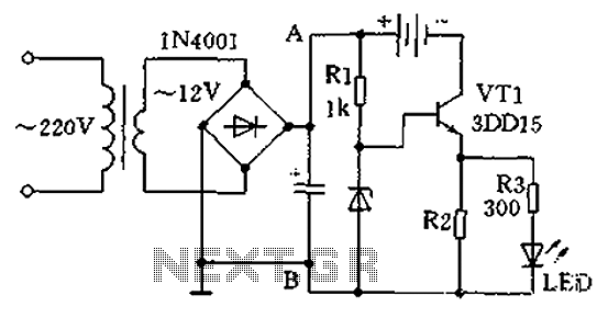
A practical single-tube constant current charger is illustrated, utilizing a transistor (VT1) that plays a crucial role in maintaining a constant current. The current value is determined by the voltage regulator and resistor R2. The general output voltage is...
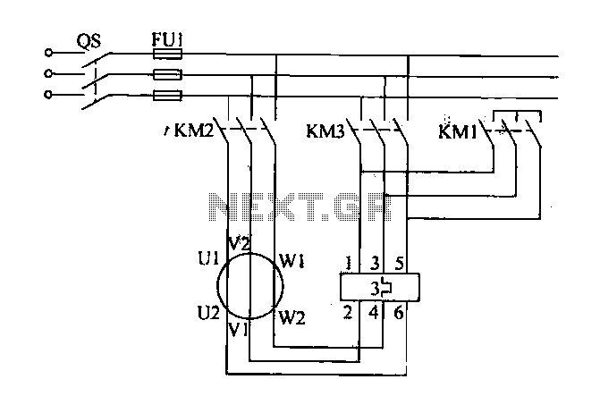
Traditional control methods for fan power equipment involve manual or relay control, which often leads to issues of poor reliability and flexibility. For instance, when the motor capacity is large, the startup process can be prolonged, resulting in high...
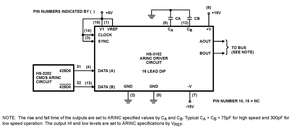
The HS-3182 is a monolithic dielectrically isolated bipolar differential line driver designed to meet the specifications of ARINC 429. This device is intended to be used with a companion chip, the HS-3282 CMOS ARINC Bus Interface Circuit, which provides...
The General Dynamic LED digital clock lacks a timekeeping function, but by adding a simple circuit, it can incorporate this feature. The integrated circuit (IC) includes a programmable mute function, which is inactive from 23:00 to 5:00 to avoid...
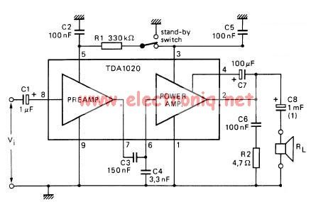
The TDA1020 is a monolithic integrated 12 W audio amplifier housed in a 9-lead single in-line (SIL) plastic package. Although it is designed primarily for car audio applications, it can also be utilized in various other audio applications. The TDA1020...
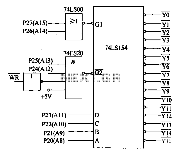
Decoding circuit: To ensure proper functionality of various interfaces, the system must assign IP addresses to all ports. Based on the number of system interfaces, it utilizes the 74LS154 decoder, which can translate up to 16 addresses. The interface...