
Address decoder interface circuit
The decoding circuit plays a critical role in managing the communication between multiple interfaces within a system. By employing the 74LS154, a 4-to-16 line decoder, the circuit can effectively assign unique IP addresses to each of the system's ports. This capability is crucial for ensuring that data packets are directed to the correct destinations, thereby maintaining the integrity of the communication process.
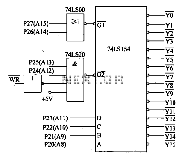
The address bus configuration, particularly the use of A15, A14, A13, and A12, enables the control of the decoder's operation. The G1 and G2 control terminals dictate whether the decoder is active, while the address lines A8 through A0 are responsible for selecting the specific output line corresponding to the desired port. This setup allows for efficient management of up to 16 different ports, facilitating a streamlined communication protocol.
Furthermore, the inclusion of eight D/A conversion circuits enhances the system's functionality by converting digital signals from the processor into analog voltages. The DAC0832 is a key component in this process, providing a reliable output range of 4-20 mA, which is standard for many industrial applications. This output can be used to control various actuators, such as motors or valves, allowing for precise manipulation of physical systems based on digital commands.
Overall, the combination of the decoding circuit and D/A conversion capabilities creates a robust framework for managing multiple interfaces and ensuring effective communication and control within the system. The design considerations and component choices reflect a thorough understanding of electronic principles and practical applications in the field.Decoding circuit: In order to make the various interfaces to work properly, the system needs to assign IP addresses to all ports. According to the number of system interfaces, it adopts the 74LS154, can be translated to 16 addresses, the interface circuit shown in Figure 27-50. The figure, the address bus A15, A14 control decoder control terminal Gl. A13, A12 control decoder control terminal G2. All-A8 connected decoder selection control terminal D, C, B, A. It can analyze each port address, see Table 27-2. In addition, the system also features eight D/A conversion circuit, respectively, to control the amount of output processor brightest converted into analog, sent to the corresponding actuators.
Use DAC0832, the output of 4-20mA.
Related Circuits
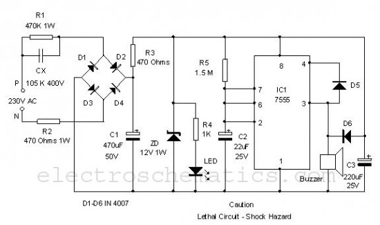
This is a simple power resumption alarm circuit that can be installed within the switch box. It emits beeping sounds when power is restored following a power outage. The power resumption alarm circuit serves as a practical solution for alerting...
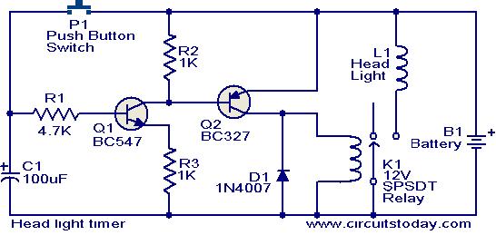
This circuit is a compact timer that keeps the headlights of a car on for approximately 1.5 minutes before turning them off. Incorporating this circuit into a vehicle allows access to dark areas without the need to return and...
The two circuits di atas illustrate opening a relay contact a short time after the ignition or light switch is turned off. The capacitor is charged and the relay is closed when the voltage at the diode anode rises...
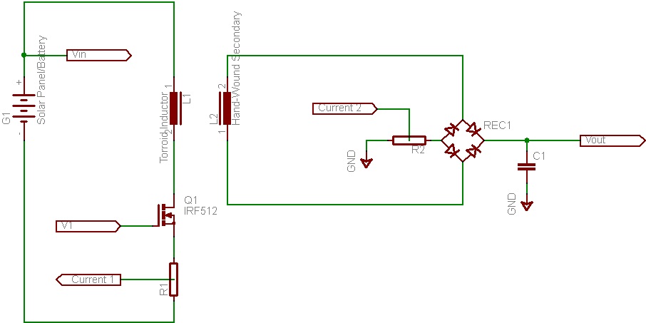
This document discusses the future direction of the Free Charge Controller project and proposes a new solar charge controller circuit. The Free Charge Controller project aims to enhance the efficiency and effectiveness of solar energy management systems. The proposed solar...

This is a design of the circuit diagram for an RS422 interface. Connector K1 is connected to the serial port of the PC, and power for the PC side of the circuit is obtained from the signal lines DTR...
This schematic represents an FM transmitter capable of delivering an output power between 3 to 3.5 W, operating within the frequency range of 90 to 110 MHz. While the stability of the circuit is acceptable, the integration of a...
Warning: include(partials/cookie-banner.php): Failed to open stream: Permission denied in /var/www/html/nextgr/view-circuit.php on line 713
Warning: include(): Failed opening 'partials/cookie-banner.php' for inclusion (include_path='.:/usr/share/php') in /var/www/html/nextgr/view-circuit.php on line 713