
Single-tube constant current charger circuit
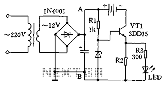
A single-tube constant current charger operates by regulating the current flowing into the battery pack using a transistor (VT1). The design features a voltage regulator that outputs approximately 3.3V, which is essential for the proper charging of nickel-cadmium batteries. Resistor R2 plays a pivotal role in setting the charging current, which can be adjusted within the range of 50mA to 80mA, depending on the specific resistance value chosen. The resistive load of R2 should be selected within the range of 30 to 60 ohms and rated for 1W to 2W to handle the power dissipation effectively.
In conjunction with the LED indicator, resistor R3, with a value between 200 to 500 ohms, is used to signal the charging status. When the circuit is operational and batteries are connected, the LED will illuminate, indicating that charging is taking place. A non-illuminating LED suggests a potential issue with the batteries, warranting further investigation.
The charger is capable of charging between 1 to 4 nickel-cadmium batteries, with a recommended charging time of approximately 12 to 14 hours, depending on the battery's state of charge and capacity. The choice of transistor, such as the 3DD15 or DS11, is critical for effective power management. It is advisable to attach a heat sink to the VT1 transistor to mitigate overheating during operation, ensuring reliability and longevity.
As there is no built-in charge control circuit, users must diligently monitor the charging time to prevent overcharging, which could lead to battery damage or reduced lifespan. This aspect emphasizes the importance of user awareness and adherence to safe charging practices when utilizing this charger design. As shown in a practical single-tube constant current charger, which play a constant role transistor VT1, its current value is determined by the voltage regulator and R2. Genera l election regulator about 3.3V, resistor R2 taken (30 to 60 Euro)/(1W ~ 2W), when the charge current is about 50mA ~ 80mA. R3 (200 ~ 500 ohms) and LED charging indicator composition circuit is connected as long as rechargeable batteries, LED will glow.
If the LED does not light, the battery is bad. The circuit of 1 ~ 4 5 nickel-cadmium batteries, charging time is 12 to 14 hours. Transistor VT1 available 3DD15 or DS11 (plastic) power management, installation, VT1 tube should be added to the radiator. Two kinds of charger neither add charge control circuit should be used to grasp the charging time, in order to ensure safe charging.
Related Circuits
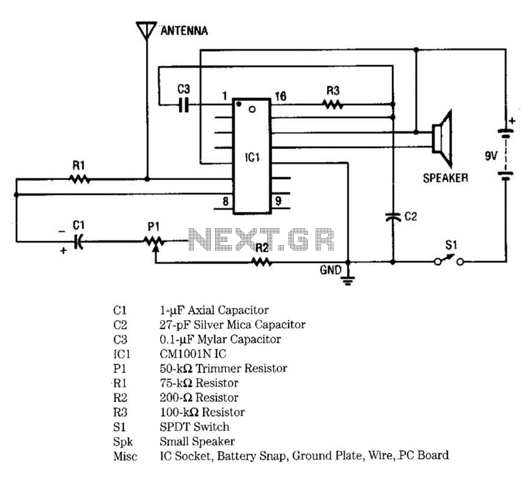
IC1 includes multiple oscillators and an amplifier. The low-frequency audio signal oscillator provides an input to the amplifier. This signal is the audio tone that is amplified and subsequently delivered to the speaker by the amplifier. The high-frequency oscillator...
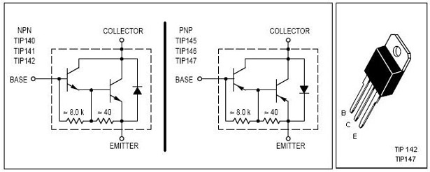
This is an economical 150 Watt amplifier circuit featuring two Darlington power transistors, TIP 142 and TIP 147. The circuit is capable of delivering up to 150 W RMS to a 4 Ohm speaker, providing substantial audio output. The...
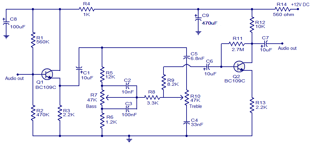
This simple tone control circuit is designed based on the renowned Baxendall tone control circuitry. The circuit can provide a maximum cut or boost of approximately 12 dB at both 10 kHz (treble) and 50 Hz (bass). Additionally, both...
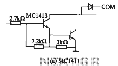
The MC1411 series is a Darlington driver with a compact, reliable internal structure. It is particularly suited for high-voltage applications, functioning effectively as a high-voltage peripheral driver. This driver can directly control relays, lights, and other loads. It is...

This is a simple smoke alarm circuit using a timer IC, the NE555. The circuit operates by illuminating a Light Dependent Resistor (LDR) with a lamp. When smoke obscures the light from the lamp, the resistance of the LDR...
A simple audio amplifier application using a TL431 voltage regulator. The amplifier is designed to produce room-filling sound from a standard clear radio equipped with a long-wire antenna and suitable ground. The chip is similar in complexity to a...