
Audio Mixer Circuit
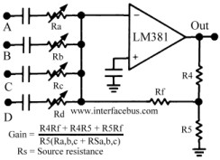
The audio mixer circuit employs the LM318 operational amplifier as the core active component, enabling the summation of multiple audio signals. The classic summing amplifier configuration allows for the mixing of signals from four audio channels, designated as A, B, C, and D. While channels A, B, and C contribute to the gain calculation, channel D serves as an illustrative example for potential channel expansion, emphasizing the circuit's scalability.
Capacitors in the circuit play a crucial role in isolating each audio channel. By blocking DC components, they prevent interference between channels while ensuring that the AC audio signals pass through with minimal loss. The selection of capacitor values is critical; a value of 1uF is commonly used to ensure compatibility with the audio frequency range, while a 0.01uF capacitor stabilizes the operational amplifier's performance by connecting the negative input to ground.
Potentiometers are integrated into the design to allow for adjustable mixing levels. The choice of potentiometer value directly influences the mixing range, with values like 100k and 500k ohms being standard. The decision between a linear potentiometer and an audio taper potentiometer affects the response characteristics, with linear potentiometers being more common in commercial applications. Consistency in potentiometer values and styles across channels is necessary to maintain uniform gain levels.
Resistors in the circuit determine the gain of the operational amplifier. The values can be adjusted to achieve the desired amplification, guided by the established gain equation. Initial resistor values such as R4 = 22k, R5 = 2.4k, and Rf = 790 ohms are suggested, specifically for channels A, B, and C.
The LM381 operational amplifier, chosen for its low noise characteristics, is utilized in a single section of the dual preamplifier. It operates with a 24-volt power supply, ensuring sufficient headroom for audio signal processing. The internal compensation of the LM381 negates the need for external frequency compensation components in the schematic. Additionally, a bypass capacitor of 0.01uF is recommended across the power supply pins to filter out noise and stabilize performance.
Overall, this audio mixer circuit schematic exemplifies a practical approach to combining multiple audio signals, providing flexibility in channel configuration, gain adjustment, and signal integrity.The circuit schematic below represents one method for the design on an audio mixer. The active component is an LM318, although basically any operational amplifier would work in its place. The circuit is the classic design for an Op Amp summing amplifier. Four individual audio channels are shown and may be mixed together. Channel D is really intend ed to show the addition of more channels and not used in the equation to calculate gain. The capacitors [C] are not used in the mixing function, but are there to DC block one channel from effecting another channel. The value of the capacitor should be selected so that it passes the signal of interest will little or no attenuation.
In the case of an audio mixer the value should be selected so that it passes the audio frequency range. The value of each capacitor should be identical for each channel, otherwise an off-set in gain will occur between the channels.
A common value found in one data sheet indicates a 1uF capacitor would work. Refer to Companies making Capacitors. A 0. 01uF capacitor is connected between the minus input and ground. The value of the potentiometer or adjustable resistor depends on the range of mixing desired and the values used for the other resistors in the circuit. Common potentiometer values include 100k and 500k ohms. A data sheet used 500k ohm values for each potentiometer. A decision also has to made regarding the style of tapper; a linear tapper or audio tapper. Refer to the Audio Amplifier topic for more information of using an audio tapper. The value and style of potentiometer should be same for each channel. Refer to Companies making Potentiometers. Note that most commercial mixing boards use a linear potentiometer which moves back and worth in a straight line, which is not the same thing as a linear tapper.
Read more about the difference in the Resistor dictionary; Linear Tapper vs. Linear Potentiometer. The resistors are used to set the gain of the Op Amp. So the values may be adjusted to produce the desired gain of the circuit, using the equation shown in the graphic. Starting values that could be used include: R4 = 22k, R5 = 2. 4k, Rf = 790 ohms. Note that the gain calculation only includes channels a, b & c, while channel `d` is only meant to show that any number of channels may be added to the circuit.
An LM381 is shown in the schematic, but may be substituted for one that is easier to procure. The LM381 is a Low Noise Dual Preamplifier, although only one section is being used in the schematic. The LM381 is only produced in a 14 pin DIP, but any package style works depending on the amplifier used.
Although not indicated in the schematic, the Op Amp design uses a 24 volt Vcc [pin 9], with pin 4 grounded. The LM381 is also internally compensated, so no frequency compensation is shown in the diagram either.
As with all operational amplifiers a by-pass capacitor of 0. 01uF should be placed between Vcc and ground. The pages provide schematic diagrams for both passive and active circuits, and in some cases a passive circuit that is also used with an active circuit [operational amplifier]. 🔗 External reference
Related Circuits
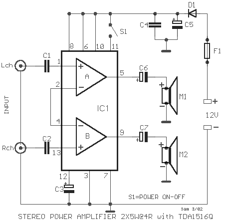
A simple stereo amplifier with minimal external components. It utilizes only one operational amplifier, which is capable of delivering an output power of 2x5W into a 4-ohm load, with a distortion of 0.5%. This stereo amplifier circuit is designed to...
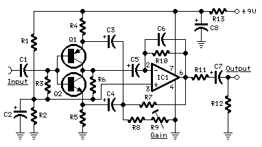
The target of this project was the design of a small portable mixer supplied by a 9V PP3 battery, keeping high quality performance. The mixer is formed assembling three main modules that can be varied in number and/or disposition...
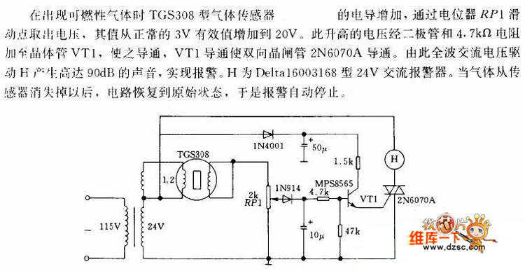
In the presence of combustible gas, the conductance of the TGS308 gas sensor increases, causing the voltage at the potentiometer RP1 slide point to rise from a normal 3V RMS to 20V. This elevated voltage is applied to transistor...
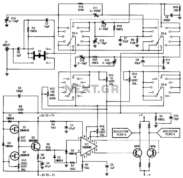
An oscilloscope front-end amplifier can be constructed using low-cost transistors and video amplifier integrated circuits (ICs). This preamplifier utilizes a FET input along with compensated attenuators, achieving an approximate bandwidth of 100 MHz, which is sufficient for most general-purpose...
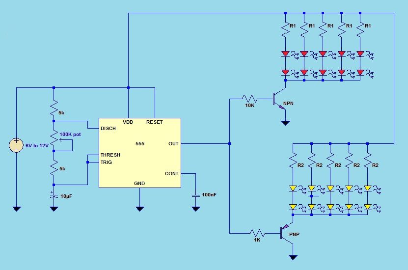
This project utilizes a 555 timer integrated circuit (IC) in an 8-pin configuration to control multiple LEDs. It is designed for quick assembly and allows for the adjustment of timing functions. The circuit employs a 555 timer in astable mode,...
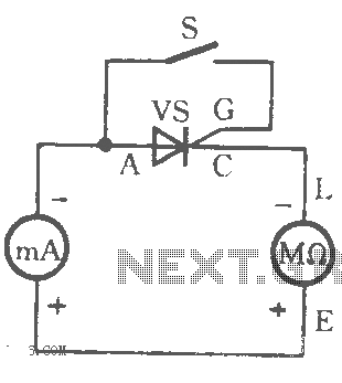
The table illustrates the capability to trigger the thyristor circuit diagram. The thyristor circuit diagram serves as a fundamental component in various electronic applications, particularly in power control and switching. A thyristor is a four-layer semiconductor device that functions as...
Warning: include(partials/cookie-banner.php): Failed to open stream: Permission denied in /var/www/html/nextgr/view-circuit.php on line 713
Warning: include(): Failed opening 'partials/cookie-banner.php' for inclusion (include_path='.:/usr/share/php') in /var/www/html/nextgr/view-circuit.php on line 713